In many OEM projects, the product development cycle follows a familiar path: engineers review available DC motors, select a motor based on its datasheet, test samples, and finalize the system design. Yet, when mass production begins, a host of unexpected problems can emerge. Some devices may fail to start, exhibit inconsistent speed, produce excessive noise, or show control instability. This often happens not because the motors are defective, but because the system was designed around a "typical" motor, failing to account for natural production variations.
A motor's nominal specification describes its intended performance, but the tolerance limits define how much that performance can realistically vary from one unit to the next. Successful OEM integration depends on designing a system that is robust enough to accommodate this variation, rather than one that only functions with a perfectly nominal motor.
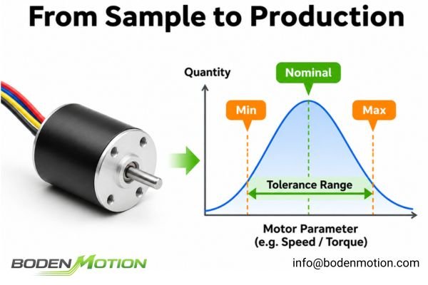
The gap between a single sample's performance and the behavior of a full production batch is where many integration projects encounter costly delays and field failures. Understanding the difference between nominal values, tolerance ranges, and the actual distribution of production parts is a critical piece of engineering discipline1. The goal is to design a system that works reliably with every motor that falls within the agreed-upon specification, not just the ones that happen to be near the average.
Nominal Values vs. Tolerance Ranges: What Is the Difference?
To manage quality and performance in mass production, it's essential to first understand the language of specifications. The terms "nominal value" and "tolerance range" describe two different but related concepts.
A nominal value describes the target for a specific parameter, while the tolerance range defines the acceptable deviation from that target. In practice, no two motors are perfectly identical, and the tolerance range provides the engineering and manufacturing guardrails for this inherent variability.
What Is a Nominal Specification?
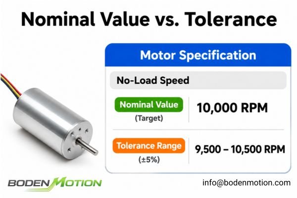
A nominal, or target, specification is the ideal value for a given motor parameter as listed on a datasheet.
- Rated Voltage: 12 V
- No-Load Speed: 10,000 RPM
- Winding Resistance: 2.0 ohms
- Motor Diameter: 16 mm
These values serve as the primary reference for design and selection. A nominal value is the specified reference, but the actual production mean may differ from this target.
What Is a Tolerance Range?
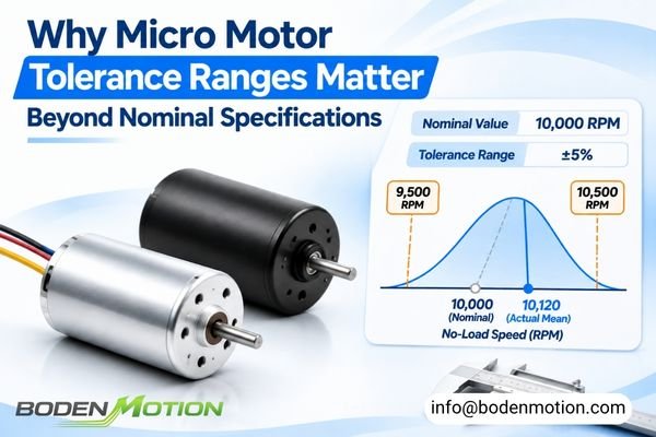
A tolerance range quantifies the permissible variation relative to the nominal value. For example, if the motor's no-load speed has a tolerance of +/- 5%:
No-load speed = 10,000 RPM +/- 500 RPM (9,500 to 10,500 RPM)
This means any motor with a no-load speed between 9,500 RPM and 10,500 RPM under the specified test conditions is considered compliant. This variation stems from minor, unavoidable differences in raw materials, winding processes, magnet characteristics, and assembly tolerances.
Key Engineering Insight:
A datasheet tolerance becomes a formal acceptance requirement when it is agreed upon and incorporated into the approved technical specification or purchasing agreement. A capable manufacturing process should maintain a production distribution that is comfortably within these agreed limits.2
Which Micro Motor Parameters Need Clearly Defined Tolerances?
Not all motor parameters are equally critical, nor should they be toleranced in the same way. A critical dimension might need a tight bilateral tolerance, while a parameter like no-load current is often best controlled with a maximum limit.
Defining the right tolerance strategy for each key parameter is crucial for system performance. Some parameters require a guaranteed minimum (like torque), while others need a strict maximum (like noise), and still others need to be controlled within a specific window (like resistance).
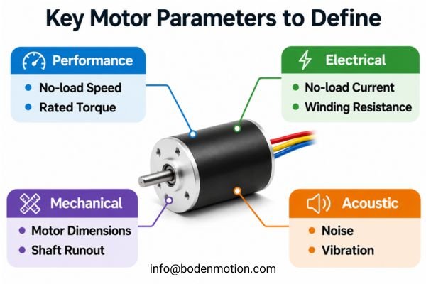
Thoughtful tolerance allocation ensures that the most critical aspects of performance are controlled without over-specifying less important ones, which can unnecessarily increase costs.
| Motor Parameter | Why Tolerance Matters | Typical Specification Approach |
|---|---|---|
| No-load speed | Affects system speed and control loop stability | Upper and lower limits (range) |
| Rated torque | Determines available torque at the operating point; together with speed, it determines mechanical output power | Minimum guaranteed value |
| No-load current | Influences standby power consumption | Maximum limit |
| Winding resistance | Affects current draw, voltage drop, copper loss, and available torque under a given supply voltage | Upper and lower limits (range) |
| Motor dimensions | Determines mechanical fit and assembly compatibility | Defined dimensional tolerances based on the mechanical interface and assembly requirements |
| Shaft runout | Influences vibration, noise, and gear alignment | Maximum allowable deviation (TIR) |
| Noise | Affects user experience and application suitability | Maximum limit under defined conditions |
| Vibration | Influences mechanical stability and system life | Defined measurement limit at key speeds |
This parameter-specific approach allows OEM engineers to focus control where it matters most. For electrical parameters, variations in resistance and back-EMF constant directly impact the motor's speed-torque curve and its response to a given voltage3. For mechanical parameters like shaft runout, tolerances dictate the smoothness and reliability of the driven system.
Bilateral, Unilateral, and Limit Tolerances: How Should Motor Specifications Be Defined?
The way a tolerance is written on a specification sheet has direct practical implications. Using the correct format ensures clarity for both the OEM designer and the motor manufacturer's quality control team.
The choice between a bilateral, unilateral, or limit tolerance depends entirely on the function of the parameter. A tolerance is only meaningful when paired with clearly defined test conditions, as a motor's performance can change significantly with voltage, temperature, or load.
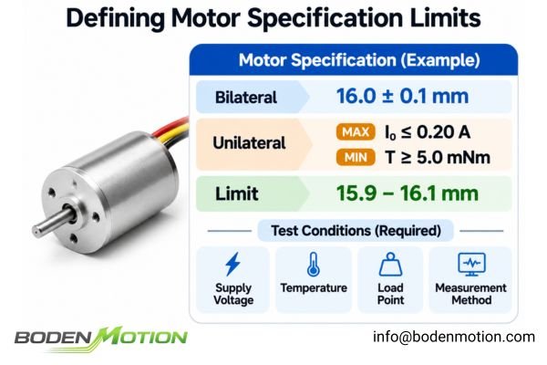
Bilateral Tolerances
This is a symmetrical tolerance, often used for dimensional parameters where deviation in either direction is equally acceptable.
D = 16.0 mm +/- 0.1 mm
Unilateral Tolerances
This type of tolerance specifies a limit in only one direction. It's ideal for parameters that should not exceed a certain value or must meet a minimum performance level.
- Maximum Limit: No-load current <= 0.20 A (e.g., for battery life)
- Minimum Limit: Rated torque >= 5.0 mNm (e.g., for guaranteed torque)
Limit Dimensions
This method explicitly states the maximum and minimum acceptable values, leaving no room for ambiguity.
15.9 mm <= D <= 16.1 mm
Real Integration Challenge:
Production noise issues can arise when a motor specification lists only a "typical" dB level. A defined maximum noise limit, tested under specific operating and measurement conditions, provides a more effective and enforceable acceptance criterion. Without defined test conditions (e.g., supply voltage, ambient temperature, load point, and measurement method), a tolerance value is incomplete.
How Motor Tolerances Accumulate Across the Complete System
A single motor can meet all its individual specifications, yet the final product can still fail. This often happens because of tolerance stacking, where the variations of multiple components combine in an unfavorable way.
A robust system design must account for the fact that a motor can meet its individual specification while the complete assembly still fails at the system level. Electrical and mechanical tolerances from the motor, power supply, driver, and mechanical linkages all interact and accumulate.
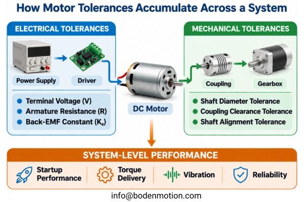
Electrical Tolerance Accumulation
The actual current a motor draws depends on the interplay of several parameters, each with its own tolerance.4 For a simplified brushed DC motor under steady-state conditions, the armature current can be approximated by:
I approx (V - Ke * omega) / R
Here, the motor terminal voltage (V), the armature resistance (R), and the back-EMF constant (Ke) all influence the operating current. A motor with resistance at the high end of its specification, combined with a power supply at the low end of its voltage range, may produce less current and electromagnetic torque under the same operating conditions. This can prevent the system from meeting its required startup or operating performance. Actual startup response should be verified under the appropriate transient and load conditions.
For a closer look at how winding resistance affects current and speed in coreless motors, see how winding resistance changes coreless motor voltage, current, and speed.
Mechanical Tolerance Accumulation
Similarly, mechanical tolerances stack up. Consider an assembly involving a motor shaft, a coupling, and a gearbox input.
- Motor shaft diameter tolerance
- Coupling inner diameter tolerance
- Gearbox input shaft tolerance
- Housing and bearing alignment tolerances
Even if each part is within its own specification, the combined effect can lead to excessive clearance or poor shaft fit, shaft misalignment, installation eccentricity, binding, and increased vibration. These issues can contribute to premature wear and reduce the reliability of the complete assembly.
Why Boundary-Condition Motors Must Be Considered During System Design
To prevent production failures, system validation must go beyond testing with a few "golden" samples. It's critical to consider how the system will perform with motors that are at the edges of their specification limits.
A robust design should be validated to work with acceptable "boundary" motors, not just with nominal or carefully selected samples. This means testing the system with motors that represent the worst-case (but still in-spec) combination of parameters relevant to the application.
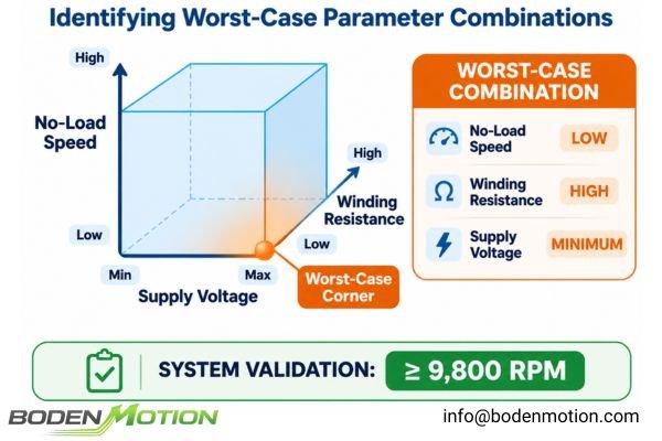
Typical Motor vs. Boundary Motor
Imagine a medical pump that must maintain at least 9,800 RPM under a defined load. The motor specification lists a no-load speed range of 10,000 to 11,000 RPM at rated voltage. A nominal sample running at 10,500 RPM no-load may meet the required operating speed under load, but this result alone does not guarantee that all in-spec motors will perform equally well.
The critical test is whether a motor near the lower end of the no-load speed range, with winding resistance near the upper specification limit and operating at the minimum expected supply voltage, can still maintain 9,800 RPM under the same load and temperature conditions. This is what boundary-condition testing is designed to verify.
Worst-Case vs. Statistical Analysis
Engineers use two main approaches to analyze the impact of tolerance stacking.
| Method | Main Purpose | Typical Use |
|---|---|---|
| Worst-case analysis | Verify operation under defined tolerance extremes. | Safety-critical systems or designs with very tight performance margins. |
| Statistical analysis | Estimate the probability of failure based on the known distribution of parameters. | High-volume production optimization and yield analysis. |
For OEM applications, worst-case analysis5 is particularly valuable for critical functions where performance margins are tight or failure consequences are significant. Statistical analysis can complement this approach when reliable production distribution data are available.
How Manufacturing Process Capability Determines Actual Motor Variation
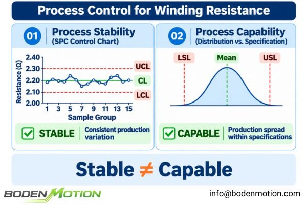
The tolerance range on a datasheet defines what is allowed, but it does not describe the actual distribution of parts from the factory. This distribution is characterized by the manufacturing process's mean, variation, and stability.
A capable and stable manufacturing process should maintain a consistent production distribution comfortably within the agreed specification limits. However, the actual production mean does not necessarily coincide with the nominal value. Understanding a supplier's process capability is key to predicting batch-to-batch consistency and long-term quality.
Sources of Manufacturing Variation
In micro motor production, variation can come from many sources:
- Inconsistent wire tension or placement during winding.
- Slight differences in magnet strength or magnetization.
- Dimensional variations in shafts, bearings, and housings.
- Minor misalignments during rotor, commutator, or brush assembly.
Process Capability Indices (Cp and Cpk)
Process capability is often measured with indices like Cp and Cpk, which compare process variation to the specification limits.
Cp = (USL - LSL) / (6 * sigma)
Cpk = min[(USL - mean) / (3 * sigma), (mean - LSL) / (3 * sigma)]
Here, USL and LSL are the upper and lower specification limits, mean is the process average, and sigma is the standard deviation.
- Cp measures potential capability by comparing the specification width with the process variation.
- Cpk also accounts for how well the process is centered within the specification limits.
These indices measure process capability but do not by themselves prove that a process is statistically stable. Capability indices are most meaningful when calculated from representative data from a stable process. Process stability must be evaluated separately using tools like Statistical Process Control (SPC) charts. While a Cp or Cpk value of 1.33 is a common benchmark, the required capability depends on application risk, industry standards, and customer requirements.
How OEM Engineers Should Define Motor Tolerance and Acceptance Requirements
A clear, well-defined specification is the foundation of a successful OEM partnership. It serves as a contract that aligns engineering requirements with manufacturing capabilities.
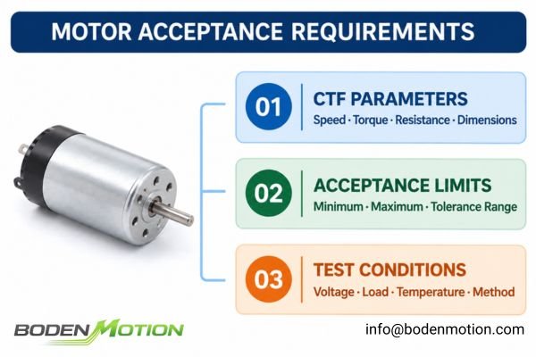
The process begins by identifying the parameters most critical to the function of your device. These "Critical to Function" (CTF) parameters should be given the tightest control and become the focus of your acceptance criteria and ongoing quality inspection.
Identify Critical-to-Function Parameters
Instead of applying a generic tolerance, prioritize what truly matters. Critical parameters should be selected based on the actual application requirements.6
| Category | Critical Parameters |
|---|---|
| Startup-critical | Starting torque, starting current, winding resistance |
| Speed-critical | Operating speed, no-load speed, back-EMF constant |
| Thermal-critical | Load current, winding resistance, duty cycle, temperature rise |
| Mechanical interface | Shaft diameter, shaft runout, mounting dimensions |
| User experience | Noise and vibration |
Thermal performance, in particular, must be evaluated under actual operating conditions rather than relying on no-load current and winding resistance alone.7
Define Acceptance and Inspection
Once critical parameters are known, an inspection plan can be created. As discussed in how to define DC motor acceptance criteria before sample approval, this involves defining the limits, test conditions, and inspection method.
| Inspection Method | Suitable Purpose |
|---|---|
| 100% inspection | For critical parameters where every unit must be individually checked due to high failure risk. |
| Sampling inspection | For routine batch acceptance using an agreed sampling plan and AQL criteria. |
| SPC monitoring | Reviewing the supplier's process control data to ensure stability. |
| Periodic validation | Conducting a full performance re-qualification on a scheduled basis. |
The right strategy depends on the application's risk, production volume, and the supplier's proven process capability.
How to Manage Motor Specification Changes Without Creating New Tolerance Risks
Finalizing a motor specification is not a one-time event. Throughout a product's lifecycle, changes in materials, processes, or even suppliers can occur, and each change carries a risk of altering the motor's performance distribution.
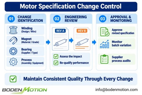
A tolerance specification is a living document that must be connected to a robust change control process. Any modification to the motor's design or the manufacturing process requires re-evaluation to ensure it doesn't negatively impact the system or introduce new batch-to-batch inconsistencies.
When Should Tolerance Limits Be Reviewed?
A formal review of the specification and a potential re-qualification of the motor is necessary when a supplier makes changes to:
- Winding design or wire type.
- Magnet material or grade.
- Bearing supplier or type.
- Shaft material or dimensions.
- Key assembly processes or equipment.
A transparent supplier will proactively notify customers of such changes, allowing for collaborative risk assessment.
Long-Term Production Consistency
Ensuring long-term consistency is one of the biggest challenges in high-volume manufacturing8. The fact that the first batch was perfect doesn't guarantee the 100,000th unit will be. Maintaining quality requires ongoing effort:
- Monitoring Batch-to-Batch Variation: Comparing inspection data from different production runs.
- Supplier Process Audits: Periodically reviewing the supplier's SPC data and quality records.
- Strict Revision Control: Ensuring that both the OEM and supplier are always working from the latest, approved version of the specification.
Conclusion
Micro motor tolerance ranges are essential to OEM success because nominal specifications alone do not describe the performance variation inherent in mass-produced components. This variation, if not properly managed, is a common source of startup failures, inconsistent performance, and system-level integration problems.
Reliable OEM integration requires clear tolerance limits, system-level analysis, and validation with boundary-condition motors. For custom motor projects, share your specifications and operating requirements with BODENMOTION. Our engineering team can help define suitable motor parameters and inspection criteria. Contact us at info@bodenmotion.com.
FAQ
Q1: What is the difference between a nominal motor specification and a tolerance range?
A nominal specification describes the target value of a parameter (e.g., 10,000 RPM), while the tolerance range defines its permitted upper and lower limits of variation (e.g., +/- 500 RPM).
Q2: Why are motor tolerance ranges important for OEM applications?
They are critical for ensuring that every motor from a production batch will function correctly within the electrical, mechanical, and performance constraints of the final device, preventing failures in mass production.
Q3: Should all micro motor parameters have the same tolerance percentage?
No. Tolerances should be assigned based on function. For example, the required tolerance for shaft diameter depends on the mechanical interface, assembly method, and application precision, and should be defined accordingly rather than using a generic value.
Q4: What is tolerance stacking in motor applications?
It occurs when the individual, in-spec variations of multiple components and operating conditions (e.g., motor resistance, power supply voltage, shaft fit, and gearbox clearances) combine to cause an out-of-spec condition in the final assembly.
Q5: What are Cp and Cpk in motor manufacturing?
They are process capability indices. Cp evaluates the potential capability of a process relative to its specification limits, while Cpk also accounts for how well the process is centered. They measure capability, not stability, which requires separate evaluation through methods like Statistical Process Control (SPC).
Q6: How can OEM engineers reduce motor performance variation in mass production?
They can work with their supplier to define clear tolerances for critical parameters, validate the system design using boundary-condition motors, and establish a robust incoming inspection plan and long-term quality monitoring process.
"Engineering Tolerances | Limits, Fits and GD&T Explained". Fractory's engineering guide explains nominal values, permissible variation, and upper and lower tolerance limits. Supports: the distinction between nominal specifications and tolerance ranges. Scope: primarily focused on dimensional tolerances. ↩
"Process Capable Tolerancing". Don Day, Martin Raines, and Ken Swift explain how design tolerances relate to manufacturing process capability, including Cp and Cpk. Supports: evaluating whether production processes can consistently meet specification limits. ↩
"FAQ: What's the Difference Between Torque Constant, Back EMF Constant, and Motor Constant?" This engineering article explains the relationships among torque, current, back-EMF, speed, and motor resistance. Supports: understanding how electrical parameters affect motor performance. ↩
"Physical Parameters Affecting Stall Torque of a Brushless DC Motor". Portescap's technical white paper analyzes how electrical parameter variations affect BLDC stall torque. Supports: understanding the combined effects of parameter variations on motor performance. Scope: focuses on BLDC motors. ↩
"Tolerance Stack Analysis Methods". Fritz Scholz presents worst-case and statistical methods for analyzing accumulated tolerances. Supports: evaluating system performance under combined component variations. ↩
"Critical Parameter Management". Don Clausing and Dan Frey explain how critical parameters govern system behavior and should be identified through functional requirements. Supports: selecting application-specific critical motor parameters. ↩
"X-57 Mod 2 Motor Thermal Analysis". NASA researchers use actual motor test data to validate thermal models and evaluate temperature behavior under operating conditions. Supports: practical motor thermal evaluation. Scope: does not directly address the limitations of no-load current and winding resistance. ↩
"Questions and Answers on Current Good Manufacturing Practice Regulations | Production and Process Controls". FDA guidance discusses process validation, batch variability, and ongoing production monitoring. Supports: maintaining consistent product quality through controlled manufacturing processes. Scope: pharmaceutical manufacturing guidance, not a motor-specific standard. ↩