A motor sample that spins is not ready for approval. Functional operation confirms basic function, but it does not establish whether future production units can be consistently measured and judged against the same application requirements.
Effective sample approval establishes a repeatable measurement and decision system. It creates a technical baseline that defines the parameters, test conditions, acceptance limits, and judgment rules used to validate a motor design and support future production quality control.
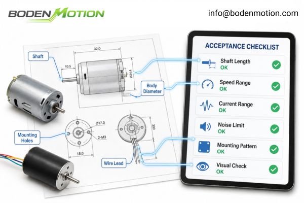
This article moves beyond a simple checklist of what to test. It explains how to connect application failure risks to measurable motor characteristics, define test conditions that make those measurements meaningful, account for measurement reliability and configuration control, and translate sample approval into a practical production-quality framework.
What "Approved" Actually Means for an OEM DC Motor
A sample is not approved simply because it runs; it is approved when the OEM and supplier agree on how to objectively distinguish an acceptable motor from an unacceptable one.
True sample approval establishes a technical baseline for the approved motor configuration. It formalizes what will be measured, how the measurements will be performed, which limits apply, and how the final decision will be made.
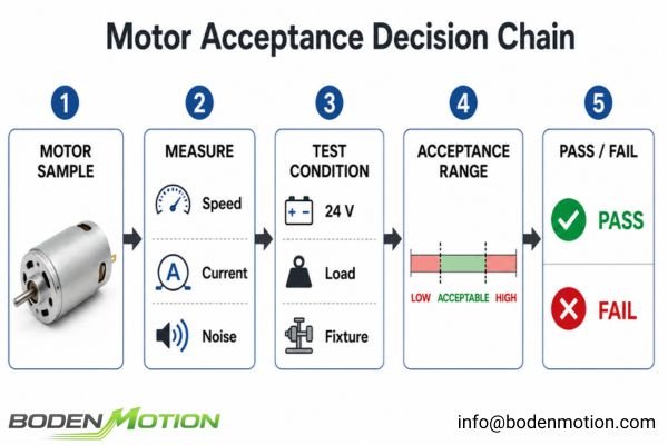
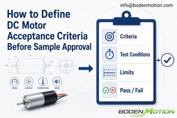
An effective approval plan should answer four core questions:
- What is being measured? For example, no-load speed, current under a defined load, startup behavior, or noise level.
- Under what conditions? For example, at a specified supply voltage, after a defined warm-up period, and on an agreed fixture.
- What are the acceptable limits? Any numerical values should be tied to the application and treated as project-specific requirements rather than generic motor-industry limits.
- How is the pass/fail decision made? For example, all motors in the defined engineering sample lot may be required to meet agreed critical criteria.
Without this level of definition, "passing" remains partly subjective. With it, sample approval becomes a repeatable engineering decision rather than a one-time judgment based on a good-performing sample1.
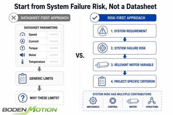
Start from System Failure Risk, Not a Datasheet
Acceptance criteria should not simply be copied from a generic supplier datasheet. They should be derived backward from the performance boundaries and unacceptable failure modes of the final application.
Before choosing individual motor limits, identify what failure looks like at the system level. A motor characteristic becomes relevant when variation in that characteristic could contribute to the identified failure or prevent the system from meeting its requirements.
For example:
- System Failure: A pump delivers inconsistent flow.
- Relevant Motor Characteristic to Verify: Speed stability under the application's changing load conditions2.
- System Failure: Battery runtime is shorter than expected.
- Relevant Motor Characteristic to Verify: Current draw across the actual operating load profile.
- System Failure: The device does not start reliably at low temperature.
- Relevant Motor Characteristic to Verify: Startup behavior at the minimum specified voltage, low temperature, and defined mechanical load.
- System Failure: The finished product is judged too noisy.
- Relevant Motor Characteristic to Verify: Sound pressure level and, where relevant, tonal noise at key operating speeds and mounting conditions3.
These relationships should not be treated as single-cause diagnoses. Pump mechanics, control algorithms, transmission components, structural resonance, and other system variables may also contribute. The purpose is to identify which motor characteristics need to be controlled as part of the complete system risk.
Core Performance Criteria and Application Robustness
Once the important system risks are understood, they can be translated into measurable motor criteria. Electrical and mechanical parameters provide a practical baseline for verifying design intent and detecting changes in manufacturing consistency.
The exact criteria depend on the motor architecture and application, but the following parameters are common starting points for building a robust acceptance plan.
| Acceptance Criterion | What to Define | Why It Matters from an Integration Perspective |
|---|---|---|
| No-Load Speed & Current | RPM range and current limit at a specified voltage | Useful indicators of winding, magnetic, friction, and assembly consistency. |
| Load Speed & Current | RPM and current limits at a defined operating torque | Confirms the motor can meet the required operating point while keeping current demand within power-system and driver limits. |
| Peak / Stall Capability | Peak torque, short-duration stall current, or other transient limits where relevant | Helps evaluate high-load events. Test duration and protection conditions must be defined because prolonged stall can thermally stress or damage a small motor4. |
| Feedback Signal | Encoder or sensor waveform, duty cycle, phase relationship, or other interface requirements | Confirms compatibility with the controller and helps prevent signal interpretation, counting, or positioning errors. |
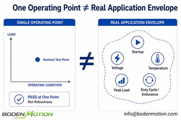
Electrical acceptance at one steady-state operating point does not establish full application robustness. Depending on the failure risks identified earlier, the validation plan may also need to address:
- minimum-voltage startup under a defined mechanical load;
- cold start and hot restart behavior;
- repeated start-stop cycling;
- short-duration peak-load events;
- operation over the real application duty cycle;
- project-specific endurance or qualification testing.
The appropriate endurance method should be defined around the expected failure mechanism, load, speed, temperature, cycling pattern, and operating environment. A fixed number of test hours alone does not demonstrate the motor's rated lifetime5.
The Hidden Variables: Defining Test Conditions
A motor that is quiet on a rigid laboratory fixture may become noticeably louder when mounted inside a thin plastic housing. The measured motor characteristic may be the same, but the system around it changes the result.
For noise, vibration, and thermal performance, the test condition is therefore part of the acceptance criterion. Mounting, load, operating speed, ambient conditions, duty cycle, and measurement location can all change the measured value.
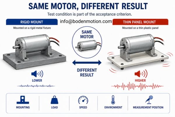
For these parameters, "how" the measurement is made is as important as "what" is measured.
Noise
Define:
- maximum sound pressure level where applicable;
- operating speed and load;
- microphone distance and angle;
- background noise condition;
- fixture or final-product mounting condition.
An illustrative noise limit such as <45 dBA is meaningful only when the associated measurement conditions are also defined.
Vibration
Specify which physical quantity is being controlled:
- Displacement: µm or mm
- Velocity: mm/s
- Acceleration: g or m/s²
These quantities are not interchangeable6. Measurement axis, operating speed, fixture stiffness, and resonance conditions should also be defined.
Temperature
Temperature-rise limits should be evaluated together with the maximum ambient temperature and the allowable absolute temperature of the relevant motor or system component7. The acceptable boundary may depend on:
- winding insulation;
- magnet temperature capability;
- bearing and lubricant limits;
- nearby electronics;
- allowable product surface temperature.
Can You Reliably Measure the Limit?
Consider a motor with an upper speed limit of 5,250 RPM. The OEM measures 5,260 RPM while the supplier measures 5,240 RPM. The disagreement may come from the motor, but it may also come from the test systems.
Before defining a narrow acceptance window, confirm that the measurement process can reliably distinguish real motor variation from test variation. Instrument accuracy alone is not enough; fixtures, operators, alignment, loading systems, warm-up procedures, and environmental conditions can also affect the result.
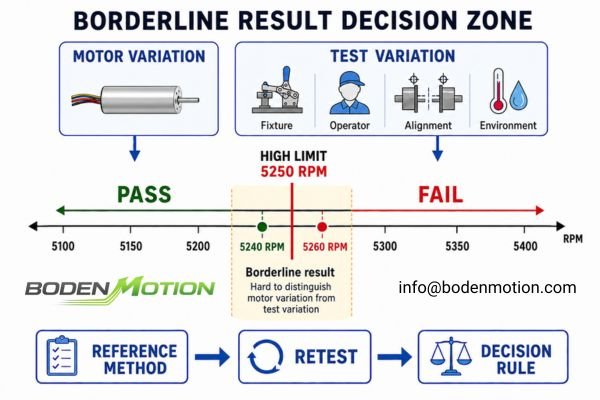
As an illustrative example, if an acceptance window is only ±3% while the combined test-system variation is already close to ±2%, distinguishing motor variation from measurement variation becomes difficult8. These percentages are examples, not universal motor-industry requirements.
The OEM and supplier should also agree on how borderline results will be handled before a disagreement occurs. The decision rule may define:
- which test method is the reference;
- whether retesting is permitted;
- how many repeated measurements may be taken;
- how measurement uncertainty is considered where relevant;
- how conflicting results between two laboratories will be resolved.
A well-defined acceptance limit without an agreed decision rule can still produce an unresolved supplier dispute9.
Freeze the Design: Configuration Control for Custom DC Motors
For a custom motor, the OEM is not approving only a model number. It is approving a controlled configuration tied to an agreed drawing revision, technical specification, critical interfaces, and relevant controlled components or materials.
Sample approval should therefore be associated with a specific revision. Otherwise, two motors carrying the same base model number may not actually represent the same configuration that was originally validated.
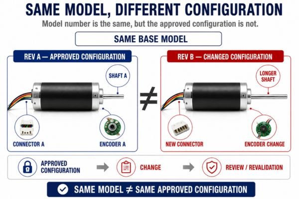
Across BODENMOTION's configurable motor platforms, application-specific differences may include winding, shaft, harness, connector, encoder, gearbox, and other interface details. These differences make revision control and change notification part of sample approval rather than simply a documentation issue.
Depending on the application, changes to characteristics such as the following may require review and partial or full revalidation:
- winding specification;
- magnet material or grade;
- bearing type or source;
- shaft material or dimensions;
- connector or harness configuration;
- encoder type or resolution;
- major assembly or testing-process changes.
This creates an important link between sample approval and change control: approval applies to a defined configuration, not indefinitely to any future motor carrying the same commercial name.
From Sample Approval to Production Control
Passing an engineering sample lot does not prove that future production will automatically remain consistent. Sample approval establishes what is acceptable; a production control plan determines how that standard will be maintained.
It is usually neither necessary nor practical to repeat every engineering-validation test on every production motor. Production controls should instead be selected according to failure risk, test cost, production volume, process capability, and customer requirements.
A production control plan may include:
- 100% End-of-Line Testing: Where justified for Critical-to-Quality characteristics.
- Sampling Inspection: Using an agreed acceptance-sampling plan for characteristics that do not require 100% inspection.
- Process Monitoring: Tracking manufacturing indicators to identify abnormal trends.
- Periodic Reliability Audits: Repeating longer-duration validation tests at defined intervals.
- Change Control: Ensuring configuration or process changes are reviewed against the approved baseline.
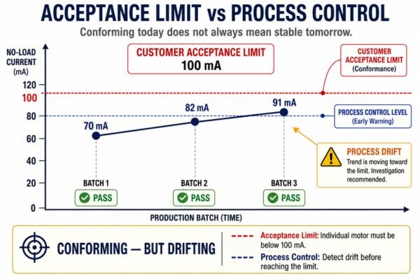
It is also important to distinguish between acceptance limits and internal process-control limits. Acceptance limits determine whether an individual motor conforms to the customer requirement. Internal process controls are intended to identify manufacturing drift before product reaches that boundary. As an illustrative example, suppose a project's no-load current specification requires each motor to remain below 100 mA. If the production average moves from 70 mA to 82 mA and then to 91 mA, every motor may still technically conform. The trend, however, could indicate a process shift that warrants investigation.
The important distinction is:
Acceptance limits determine whether individual motors conform. Process controls help determine whether the manufacturing process is moving toward future nonconformance10.
Micro DC Motor Sample Acceptance Checklist
A useful sample-approval checklist should do more than record whether several measurements passed. It should preserve the technical baseline needed to transfer engineering approval into production-quality management.
The production-control methods shown below are examples rather than universal requirements. The final plan should be determined according to application risk, motor design, production volume, test capability, and agreed customer requirements.
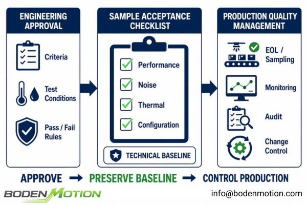
| Category | Acceptance Criterion | Test Condition / Method | Sample Judgment | Example Production Control |
|---|---|---|---|---|
| Performance | No-load and load speed/current ranges | Defined voltage, load, fixture, and warm-up state | Pass/fail against agreed range | EOL test or sampling, depending on risk |
| Startup | Reliable start under defined load and minimum specified voltage | Defined startup load, voltage, and relevant temperature condition | Meets agreed startup requirement | Qualification or periodic audit |
| Noise | Maximum permitted sound level or tonal characteristic | Defined speed, load, mounting, distance, and environment | Must remain within defined limit | Sampling or EOL where practical |
| Vibration | Defined displacement, velocity, or acceleration limit | Specified speed, measurement axis, mounting, and fixture condition | Must remain within agreed limit | Sampling or periodic audit |
| Thermal | Temperature rise and absolute-temperature limits | Defined load, duty cycle, ambient condition, and measurement point | Both limits remain within agreed boundaries | Qualification or periodic thermal audit |
| Reliability | Project-specific endurance or qualification requirement | Defined load, speed, environment, duty cycle, cycling pattern, and validation method | No defined failure; post-test performance remains within agreed degradation limits | Reliability monitoring |
| Interface / Feedback | Connector, wiring, encoder, or sensor signal requirements | Visual, electrical, waveform, phase, or signal verification as applicable | Must match approved interface definition | EOL electrical check or configuration verification |
| Configuration | Shaft, dimensions, wire, connector, gearbox, revision, and other controlled features | Approved drawing/specification and appropriate inspection method | Must match approved revision | Revision control, change notification, and incoming verification where required |
The checklist should be finalized before sample approval, not reconstructed after production has already begun. That makes it a common reference for the OEM's engineering, procurement, and quality teams, as well as the motor supplier.
Conclusion
DC motor sample approval is not simply a test event. It establishes a repeatable engineering framework that connects application risk, measurable limits, test conditions, measurement capability, decision rules, configuration control, and future production quality management.
For customized motor projects, defining this framework before final approval helps reduce ambiguity as production scales. BODENMOTION can work with OEM engineering teams to review operating conditions, configuration requirements, and validation priorities before the acceptance baseline is finalized. Contact: info@bodenmotion.com
FAQ
Q1: What are DC motor acceptance criteria?
DC motor acceptance criteria are predefined, measurable requirements used to decide whether a motor sample meets the agreed application and engineering requirements. They may include electrical performance, startup behavior, NVH, thermal performance, reliability, interfaces, and configuration requirements.
Q2: Why is it not enough for a motor sample to simply run?
Basic operation proves only that the motor functions. It does not demonstrate performance under the real load profile, startup robustness, thermal behavior, measurement consistency, long-term reliability, or future production repeatability.
Q3: What should be included in a motor sample test plan?
A robust plan should define the test items, test conditions, acceptance limits, measurement methods, engineering sample quantity, approved configuration, and pre-agreed rules for pass/fail and borderline results.
Q4: Why can my motor test results differ from the supplier's?
Different results can come from the motor itself or from differences in the test process. Common sources include power-supply conditions, fixture alignment, load application, measurement equipment, ambient temperature, warm-up time, and measurement procedure. This is why the test method and decision rule should be agreed together with the numerical limit.
Q5: Should a customized motor use the same acceptance criteria as a standard catalog motor?
Not necessarily. A catalog motor datasheet provides a useful starting point, but a customized motor may operate at a different voltage, load point, duty cycle, temperature, or performance target. Its final acceptance criteria should therefore be validated against the actual application and approved configuration.
"Preliminary Design Review (PDR) | www.waru.edu", https://www.waru.edu/acquipedia-article/preliminary-design-review-pdr. Industry standards and engineering quality literature emphasize that well-defined approval criteria enable repeatable and objective decision-making in product qualification processes. Evidence role: expert_consensus; source type: education. Supports: With clear approval criteria, sample approval becomes a repeatable engineering decision rather than a subjective, one-time judgment.. Scope note: The support is general to engineering and quality assurance fields, not specific to motor approval plans. ↩
"Stability Analysis of the Output Speed in a Hydraulic System Powered by ...", https://www.mdpi.com/2075-4442/12/3/64. A technical review of electric motor performance highlights that speed stability under varying load conditions is a critical parameter affecting system reliability, particularly in applications such as pumps where inconsistent flow can result from speed fluctuations. Evidence role: mechanism; source type: education. Supports: Speed stability under the application's changing load conditions is a relevant motor characteristic to verify when a pump delivers inconsistent flow.. Scope note: The source discusses general principles and may not address every specific pump application. ↩
"Understanding the Operating Noise of Electric Motors - CADFEM Blog", https://blog.cadfem.net/en/understanding-the-operating-noise-of-electric-motors. Engineering literature on electric motor noise identifies sound pressure level and tonal noise as key metrics for evaluating and controlling perceived noise in finished products, especially at specific operating speeds and mounting configurations. Evidence role: mechanism; source type: education. Supports: Sound pressure level and tonal noise at key operating speeds and mounting conditions are relevant motor characteristics to verify when a finished product is judged too noisy.. Scope note: The literature provides general guidance and may not address all device types or mounting scenarios. ↩
"Equipment Damage Curves Motors - SKM Systems Analysis", https://www.skm.com/applicationguides10.html. Technical literature on electric motors explains that prolonged stall conditions can lead to excessive heat buildup, potentially causing thermal damage to small motors due to increased current draw and lack of cooling. Evidence role: mechanism; source type: education. Supports: prolonged stall can thermally stress or damage a small motor.. Scope note: The extent of damage depends on motor design and protection features. ↩
"[PDF] Reliability Life Testing and Evaluation of 3-Phase Motors - Purdue e-Pubs", https://docs.lib.purdue.edu/cgi/viewcontent.cgi?article=1376&context=icec. Engineering standards and reliability research indicate that a fixed-duration test may not capture all failure modes or accurately predict the rated lifetime of a motor, as lifetime depends on various operational and environmental factors. Evidence role: expert_consensus; source type: research. Supports: A fixed number of test hours alone does not demonstrate the motor's rated lifetime.. Scope note: Support is contextual, as some standards may use fixed-hour tests as part of broader qualification protocols. ↩
"Experimental Design for Three Vibration Experiments", https://www.sjsu.edu/ae/docs/project-thesis/Rahul.Sharma-F21.pdf. Technical standards and engineering literature clarify that displacement, velocity, and acceleration in vibration measurement represent distinct physical quantities and are not interchangeable, as each describes different aspects of vibratory motion. Evidence role: definition; source type: education. Supports: These quantities are not interchangeable.. Scope note: The source may provide general definitions rather than application-specific guidance. ↩
"Extend the Operating Life of Your Motor", https://www.energy.gov/sites/prod/files/2014/04/f15/extend_motor_operlife_motor_systemts3.pdf. Engineering standards for electric motors recommend evaluating temperature-rise limits in conjunction with maximum ambient temperature and the allowable absolute temperature of the motor or system component to ensure safe operation. Evidence role: expert_consensus; source type: institution. Supports: Temperature-rise limits should be evaluated together with the maximum ambient temperature and the allowable absolute temperature of the relevant motor or system component.. Scope note: The recommendation may be specific to certain types of motors or components as defined in the standard. ↩
"Measurement Uncertainty | Bio-Rad", https://www.bio-rad.com/en-us/resources/quality-controls/qc-resources/measurement-uncertainty. Metrology and quality control literature explain that when the combined measurement system variation approaches the acceptance window, it becomes challenging to separate product variation from measurement variation. Evidence role: mechanism; source type: education. Supports: If the combined test-system variation is close to the acceptance window, distinguishing motor variation from measurement variation becomes difficult.. Scope note: The support is general to measurement science and not specific to the motor industry. ↩
"Simple Acceptance Decision Rule Examples - ISOBudgets", https://www.isobudgets.com/simple-acceptance-decision-rule-examples/. Industry standards and quality management literature note that the absence of a clear decision rule, even when acceptance limits are specified, can lead to unresolved disputes between suppliers and OEMs regarding product conformity. Evidence role: expert_consensus; source type: education. Supports: A well-defined acceptance limit without an agreed decision rule can still produce an unresolved supplier dispute.. Scope note: The support is based on general industry practice and quality management principles, not a specific case study. ↩
"Manufacturing Process Control: Its Role In Your Factory", https://qualityinspection.org/manufacturing-process-control-china/. Process control methods are widely used in manufacturing to monitor process stability and detect trends that may lead to nonconformance, as described in statistical process control literature. Evidence role: mechanism; source type: education. Supports: Process controls help determine whether the manufacturing process is moving toward future nonconformance.. Scope note: The source may provide general principles of process control rather than specific examples related to electric motors. ↩