The demand for faster, more responsive motion systems is a constant driver in the design of precision automation, medical equipment, high-speed actuators, and portable electronic devices. Miniature Coreless Motors are often the preferred choice for these applications due to their low rotor inertia and high power density. However, pushing a motor into the high-speed operating range introduces a host of engineering challenges that go far beyond simple torque and speed calculations.
A motor that performs well at moderate speeds may become mechanically unstable, acoustically noisy, or thermally limited when operated at much higher RPM. High-speed motor selection requires a holistic approach that considers not only the motor's diameter and rated speed but also its rotor structure, bearing system, dynamic balance, mechanical strength, and thermal management capabilities.

As rotational speeds climb, factors like rotor centrifugal stress, sensitivity to dynamic imbalance, bearing loads, and friction-related losses become dominant constraints. Simply choosing a motor based on its datasheet's maximum speed rating is rarely sufficient for building a reliable, long-lasting high-speed device1.
Why High-Speed Operation Changes Coreless Motor Size Selection
At low to moderate speeds, motor selection often prioritizes torque output and package size. At high speeds, the primary concerns shift toward mechanical integrity and dynamic stability. The physics of high-speed rotation fundamentally alters the design trade-offs.
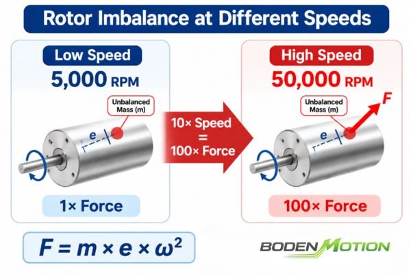
As rotational speed increases, forces generated by even minuscule imbalances in the rotor grow with the square of the speed, placing significant stress on the bearings and the entire motor structure. This means the mechanical design limitations, not just the electromagnetic ones, often dictate the motor's true high-speed potential.
The Relationship Between RPM and Mechanical Stress
The centrifugal force generated by an unbalanced mass in a rotor is described by the relationship:
Where:
- F is the centrifugal force.
- m is the unbalanced mass.
- e is the distance of the mass from the axis of rotation (eccentricity).
- ω is the angular velocity.
This equation shows that the force increases with the square of the rotational speed. A small imbalance that is negligible at 5,000 RPM can become a source of destructive vibration and bearing load at 50,000 RPM. This is distinct from the general centrifugal stress experienced by the entire rotor structure, which also increases with speed and must be managed to prevent mechanical deformation.
High-Speed Design Trade-Offs
While a smaller rotor may have lower inertia, which is beneficial for acceleration, it does not automatically make it a better choice for high-speed operation. The selection of motor diameter and length involves a complex set of trade-offs between mechanical strength, thermal performance, and electromagnetic capability3, which becomes more critical as speeds rise.
How Motor Diameter and Length Affect High-Speed Performance
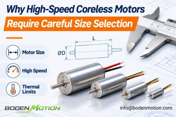
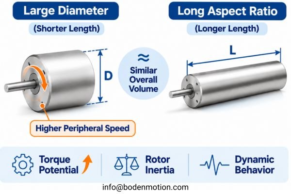
The physical dimensions of a motor—its diameter and active length—directly influence its suitability for high-speed applications. Each dimension presents a different set of trade-offs related to mechanical stress, torque production, and rotational dynamics.
In general, a larger motor diameter increases the potential for torque but also raises the rotor's peripheral speed and associated mechanical stresses at a given RPM. A longer motor can also increase torque, but its effect on rotor stiffness and dynamic behavior is complex and depends on the overall design.
Motor Diameter and Peripheral Speed
A larger diameter increases the volume of the electromagnetic circuit, which can improve torque capability.4 However, it also means the rotor surface travels at a higher linear velocity. This peripheral speed is given by:
v = (π × D × n) / 60
Where:
- v = rotor peripheral speed (m/s)
- D = rotor diameter (m)
- n = rotational speed (RPM)
A higher peripheral speed contributes to greater structural stress on the rotating components, which must be accounted for in the rotor's mechanical design and material selection.5
Active Length
Increasing the active length of the motor can also increase torque output. However, its influence on rotor dynamics is highly dependent on shaft geometry, bearing arrangement, and mass distribution. A longer unsupported shaft span can reduce stiffness and lower the system's critical speed, but a longer motor body does not automatically lead to inferior dynamic performance if designed correctly.
Diameter vs. Length: A Comparison
| Design Factor | Larger Diameter | Longer Motor |
|---|---|---|
| Rotor peripheral speed | Higher at the same RPM | Not directly increased |
| Rotor inertia | Tends to increase significantly | Tends to increase moderately |
| Torque potential | Can increase significantly | Can increase |
| Mechanical design | Requires robust management of radial stresses and hoop strength | Requires careful design for axial stiffness and rotor dynamics |
These are general trends; the final performance depends on the specific rotor structure, winding distribution, magnetic circuit, and mechanical construction.
Why Rotor Dynamic Balance Becomes Critical at High RPM
At high speeds, a crucial factor for mechanical stability and low vibration is the dynamic balance of the rotor. A well-balanced rotor will spin about its central axis with minimal force exerted on the bearings.
Even small, nearly undetectable manufacturing deviations in mass distribution can produce disproportionately large vibration and noise at high RPM. For this reason, high-speed motors often require tighter balancing tolerances or lower permissible residual unbalance. The appropriate balance quality grade depends on rotor mass, operating speed, rotor configuration, and application requirements.

Static, Couple, and Dynamic Unbalance6
- Static Unbalance: Occurs when the rotor's center of mass is offset from the axis of rotation. This can be detected when the rotor is stationary.
- Couple Unbalance: Occurs when two equal unbalance masses are located at opposite ends of the rotor and 180 degrees apart, creating an unbalanced moment or "wobble" when spinning.
- Dynamic Unbalance: The combination of static and couple unbalance. Correcting it requires measuring forces while the rotor is spinning and removing or adding mass in at least two separate planes along its length.
Sources of Rotor Imbalance
- Uneven winding distribution in the self-supporting coil.
- Slight eccentricity of the rotor relative to the shaft.
- Minor variations in the density of materials.
- Assembly and manufacturing tolerances.
As explored in discussions on why coreless motors shake at high speed, these residual imbalances lead directly to increased vibration, acoustic noise, premature bearing wear, and a reduction in overall operational stability.
How Bearing Selection Limits High-Speed Coreless Motor Reliability
The bearings are the direct interface between the rotating shaft and the stationary housing. Their performance and longevity are paramount in any high-speed application.
A high-speed motor is only as reliable as its complete rotating support system. The bearing system must be carefully selected to handle the target rotational speed, expected loads, and operating temperature for the required lifetime of the device.

Bearing Selection Criteria
The suitability of a bearing system for high-speed operation depends on a combination of factors:
- Bearing Design and Dimensions: Different bearing types (e.g., ball, sleeve) and sizes have different speed capabilities.
- Speed Rating: Manufacturers specify speed limits based on thermal and mechanical constraints.
- Internal Clearance or Preload: The correct clearance is needed to accommodate thermal expansion without causing excessive play or binding.
- Lubrication: The type, quantity, and viscosity of grease or oil are critical and can degrade quickly at high speeds and temperatures.
- Operating Temperature: Excessive heat accelerates lubricant breakdown and can alter bearing dimensions.
Interaction of Speed and Load
External loads from belts, gears, or other driven mechanisms directly affect bearing wear. While high rotational speed does not amplify these external forces, it introduces additional challenges from friction, heat, and lubrication stress. The combination of these factors determines the bearing's ultimate service life. As noted in the analysis of why mini brushless motors need better bearings, a system adequate for low-speed use can fail quickly under the combined demands of high RPM and external loading.
How Shaft Design and Rotor Structure Affect the Safe Operating Speed
Beyond the bearings, the mechanical design of the shaft and the structural integrity of the rotor itself are fundamental to safe high-speed operation. This is an area where the architecture of the motor—brushed or brushless—creates important distinctions.
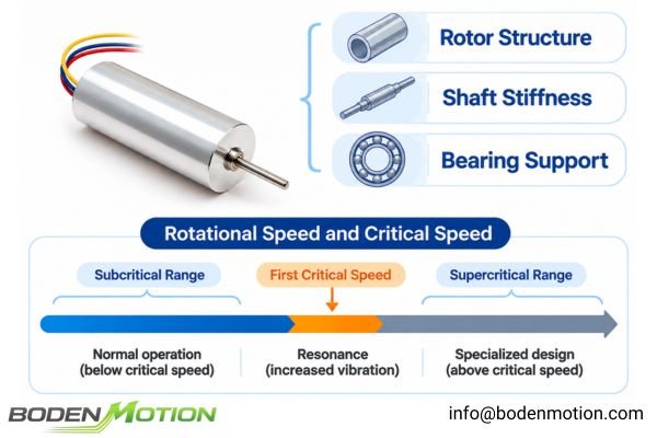
The safe operating speed is determined by the complete rotating assembly, not by the motor's electromagnetic capability alone. The rotating components must be strong enough to withstand immense centrifugal forces without deforming or failing.
Rotor Structural Integrity
- Brushed Coreless DC Motors: The self-supporting winding coil is the rotor. At high speeds, centrifugal forces act directly on this winding, testing the strength of its bonding materials.
- Coreless BLDC Motors: In the common architecture, the winding is stationary, and the permanent magnet assembly is the rotor. Here, the primary concerns are the retention of the magnets on the shaft and the structural integrity of the rotor hub and associated components.
Critical Speed and Rotor Dynamics
Rotating systems have natural vibration modes. A critical speed occurs when the rotational excitation frequency coincides with a relevant natural frequency, potentially producing resonance and increased vibration.7
The critical speeds depend on factors such as rotor mass and mass distribution, shaft stiffness (influenced by shaft diameter and material), bearing span, and support stiffness.
For many miniature motor applications, a subcritical design is preferred, with the normal operating range kept sufficiently below the first relevant critical speed.8 While some specialized systems are designed to operate above a critical speed (supercritical operation), this requires careful engineering to safely pass through the resonance region and maintain stable operation.
Why Thermal and Electrical Limits Still Matter in High-Speed Motor Selection
While mechanical factors are often the primary concern, the electrical and thermal performance of the motor cannot be ignored in high-speed applications.
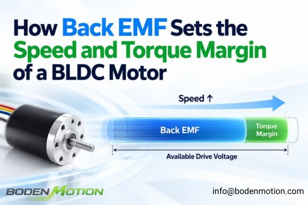
As speed increases, the back-EMF generated by the motor rises, which can limit the voltage available for generating torque. At the same time, high-speed operation introduces additional sources of heat from mechanical losses, which must be managed to prevent overheating.

High-Speed Electrical Requirements
As a motor spins faster, it generates a back-EMF that opposes the supply voltage. At very high speeds, this back-EMF can become nearly equal to the supply voltage9, leaving very little "voltage headroom" for the controller to drive torque-producing current through the windings. This can limit the motor's ability to accelerate or respond to changes in load.
Heat Generation at High RPM
Heat in a motor comes from multiple sources:
- Copper Losses (P_cu = I² × R): Heat generated in the windings due to current flow. This is load-dependent.
- Mechanical Losses: Bearing friction and windage (air drag on the rotor) generally increase as rotational speed rises, although their actual behavior depends on bearing design, lubrication, rotor geometry, and operating conditions.
- Brush Friction: In brushed coreless motors, friction between the brushes and commutator is a significant speed-dependent heat source.
High-speed operation does not automatically mean the motor will run hotter. The final temperature depends on the actual load current, duty cycle, the magnitude of mechanical losses, and the device's ability to dissipate heat.
How OEM Engineers Should Select and Validate a High-Speed Coreless Motor
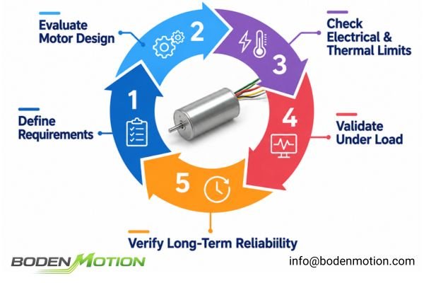
Selecting a high-speed coreless motor is a systematic process of matching the motor's comprehensive capabilities with the application's specific demands.
A successful high-speed design requires moving beyond datasheet values and performing rigorous validation. This involves testing the motor under actual load conditions to evaluate its dynamic stability, thermal performance, and long-term reliability.
High-Speed Motor Selection Checklist
| Selection Factor | Information to Define |
|---|---|
| Motor diameter | Maximum allowable diameter |
| Motor length | Available axial installation space |
| Operating speed | Continuous and peak RPM |
| Torque | Continuous and peak torque at speed |
| Rotor balance | Required balance quality or permissible residual unbalance |
| Bearing system | Speed rating, preload, and expected lifetime |
| Shaft design | Diameter, material, and external loading |
| Thermal conditions | Ambient temperature and available cooling |
| Duty cycle | Continuous or intermittent operation |
| Vibration/Noise | Allowable levels for the application |
| Lifetime | Expected total operating hours |
| Motor architecture | Brushed or brushless |
Practical Validation Process
- Define the target continuous and peak RPM and the torque required at those speeds.
- Confirm available installation dimensions.
- Evaluate candidate motors for their rotor balance quality, bearing system, and structural design.
- Check that the supply voltage and driver are sufficient to overcome back-EMF and provide the necessary current.
- Perform thermal testing at the intended duty cycle and load to ensure the motor operates within its temperature limits.
- Test vibration and acoustic noise across the entire operating speed range.
- Validate long-term continuous operation to confirm bearing and lubricant reliability.
Conclusion
High-speed coreless motor selection requires more than matching the motor diameter to the available installation space or picking a motor with a high maximum RPM rating. As rotational speed increases, a complex interplay of mechanical and electrical factors—including rotor dynamic balance, bearing limitations, shaft dynamics, and thermal performance—comes to the forefront. These factors, not the motor's raw power, often become the true determinants of reliability and success.
A smaller motor may offer lower rotor inertia, but it does not automatically provide better high-speed stability. The most suitable configuration is one that balances motor dimensions, mechanical robustness, electrical efficiency, and expected operating lifetime. For OEM engineers developing high-speed motion systems, evaluating these factors under actual operating conditions is essential before finalizing a motor configuration. If you are looking for a suitable high-speed coreless motor or require a customized solution, contact the BODENMOTION engineering team at info@bodenmotion.com to discuss your target RPM, torque requirements, installation dimensions, and application conditions.
FAQ
Q1: What determines the maximum speed of a coreless motor?
The true maximum speed is determined by the most restrictive of several combined factors: the rotor's mechanical strength, dynamic balance quality, bearing system capabilities, shaft dynamics (critical speed), electrical limitations (back-EMF), and thermal limits.
Q2: Does a smaller coreless motor always support higher RPM?
Not necessarily. While a smaller rotor may have lower inertia, its potentially smaller bearings, less rigid shaft, and reduced heat dissipation capability can impose their own limitations on safe, continuous high-speed operation.
Q3: Why is rotor balancing important in high-speed motors?
Even tiny mass imbalances generate centrifugal forces that increase with the square of the rotational speed. At high RPM, these forces can cause significant vibration, acoustic noise, and rapid bearing wear.
Q4: Do high-speed coreless motors require special bearings?
The appropriate bearing system depends on the specific speed, loading, temperature, and lifetime requirements of the application. While high-speed applications often use high-precision ball bearings with special lubrication, the optimal choice must be engineered for the specific context.
Q5: Can a coreless motor run continuously at its maximum speed?
This depends on how the manufacturer defines the speed specifications:
- No-load Speed: The motor's rotational speed without an external mechanical load under specified voltage and control conditions.
- Rated Speed: The speed associated with the manufacturer's rated operating point under specified load and electrical conditions. It represents a continuous operating point only when the manufacturer specifies it as such.
- Maximum Permissible Speed: The upper mechanical or operational speed limit defined by the manufacturer under specified conditions. It should not automatically be treated as a continuous operating rating.
- Maximum Continuous Operating Speed: The highest speed at which the motor is specified to operate continuously while meeting its thermal, mechanical, and service-life requirements under defined operating conditions.
OEM engineers should confirm the manufacturer's definitions and the applicable load, duty cycle, temperature, and lifetime conditions before selecting a motor for continuous high-speed operation.
Q6: What information is needed to customize a high-speed coreless motor?
Key information includes the target continuous and peak RPM, required torque, available motor dimensions, operating duty cycle, bearing and lifetime requirements, acceptable vibration and noise limits, and details of any external loads on the shaft.
PMD, "Principles of Motor Selection." Explains that motor selection requires consideration of operating conditions and overall system requirements beyond the maximum speed rating. Supports the need for comprehensive evaluation when selecting motors for high-speed applications. ↩
University Physics Volume 1, "6.3 Centripetal Force." Explains the relationship between rotational speed, mass, and radius in a rotating system. Supports the formula F = m × e × ω² and the square-of-speed relationship for the force generated by rotor imbalance. ↩
CTI Symposium, "Overcoming Challenges to High-Speed Electric Motors." Discusses the engineering trade-offs between mechanical strength, thermal performance, and electromagnetic capability in high-speed motor design. ↩
MIT OpenCourseWare, "6.685 Electric Machines, Course Notes 1: Electromagnetic Forces." Explains electromagnetic force generation in electric machines and provides theoretical support for the relationship between motor geometry and torque capability. ↩
MIT Energy Initiative, "Designing High-Speed Motors for Energy Storage and More." Discusses the mechanical challenges associated with high-speed motor design, including peripheral speed, rotor structural stress, and material selection. ↩
HAIMER, "Fundamentals of Tool Balancing." Explains static, couple, and dynamic unbalance, including the principles of two-plane rotor balancing. Supports the classification and correction of rotor imbalance. ↩
CBM CONNECT, "Understanding Critical Speed in Rotating Machinery." Explains the relationship between critical speed, natural frequency, and resonance, supporting the importance of avoiding unstable operating speed ranges. ↩
Alícia Santarén Rodríguez, "Dynamic Behaviour of High-Speed Rotor," Aalto University (2017). Examines rotor dynamics, critical speeds, and subcritical and supercritical operating conditions. Supports maintaining sufficient separation between operating speed and critical speed. The study focuses on a high-speed electric motor, not miniature coreless motors. ↩
OpenStax, "23.6 Back Emf – College Physics." Explains how back-EMF increases with motor speed and can approach the driving voltage under no-load conditions, reducing the voltage available to drive winding current. ↩