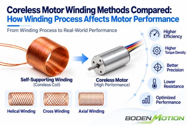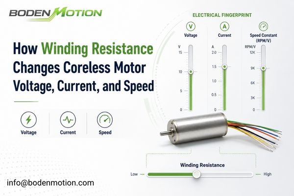
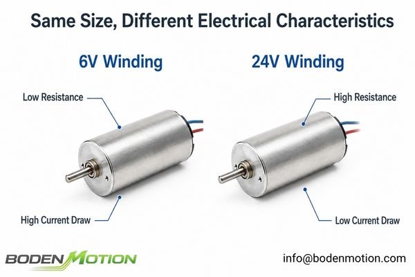
Two coreless motors with the same dimensions can behave very differently because their windings are different. This often leads to confusion and incorrect motor selection in OEM projects.
Different voltage versions of the same coreless motor (e.g., 6V, 12V, 24V) have different winding resistances and motor constants, which fundamentally change their speed, current draw, and thermal behavior for a given mechanical load.
In OEM projects, engineering teams sometimes select a motor based on its physical size and nominal voltage, only to find that it draws too much current or fails to reach the target speed. The reality is that changing a motor's winding involves altering the number of turns and wire diameter, which impacts resistance, back-EMF, and the torque constant. The question isn't whether a 24V version is "more powerful," but rather, "which winding best matches my available voltage, required speed, torque, and current limit1?"
What Determines Winding Resistance in a Coreless Motor?
Winding resistance isn't just an arbitrary datasheet value; it's a direct result of the coil's physical construction. Forgetting this link can lead to misinterpreting a motor's electrical characteristics.
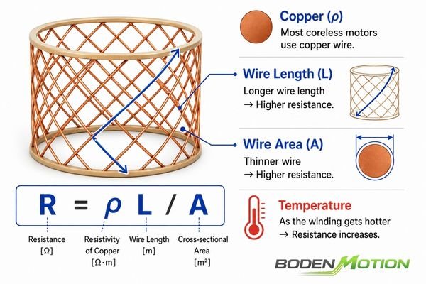
In a coreless motor, winding resistance is primarily determined by the conductor's material (usually copper), its total length (number of turns), and its cross-sectional area (wire diameter).
The relationships below use a simplified DC motor model to explain the core principles. These same principles also apply to coreless BLDC motors, although the exact voltage and current relationships will also depend on phase configuration, commutation method, and the driver's control strategy.
At a basic level, resistance is governed by:
- Conductor Material: Nearly all high-performance coreless motors use copper.
- Total Wire Length: More turns require a longer piece of wire, which increases resistance.
- Wire Diameter (Gauge): Thinner wire has a smaller cross-sectional area, which increases resistance.
- Winding Temperature: As the motor heats up, the resistance of the copper winding increases.2
When we create different voltage versions of the same motor platform, we are constrained by the fixed amount of space available for the coil. This leads to a common design trade-off:
- Higher-Voltage Winding (e.g., 24V): To operate effectively on a higher voltage supply, the winding typically uses more turns. To fit these extra turns into the same available winding volume, it typically uses thinner wire. Both factors—greater conductor length and smaller cross-sectional area—tend to increase the winding resistance.
- Lower-Voltage Winding (e.g., 6V): This version is designed for lower voltage and higher current. It typically uses fewer turns of thicker wire, resulting in a lower winding resistance.
Design Trade-Off: The available winding volume is finite. You can't have both a high number of turns and a very thick wire. This fundamental constraint is why different voltage windings on the same motor frame typically exhibit different resistance and current characteristics.
How Winding Resistance Changes Motor Current
A motor's winding resistance has a direct and immediate impact on its current draw, especially under high load or during startup.
At stall or very low speed, assuming no active current limiting, winding resistance becomes a major factor limiting current, giving the simplified approximation I ≈ V / R.
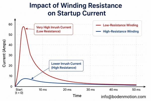
In a real system, startup current is also affected by winding inductance, driver current limiting, PWM duty cycle, and power supply impedance. However, the V/R approximation is a useful tool for estimating the theoretical steady-state stall current under full applied voltage when active current limiting is absent.
This can be verified using the BODENMOTION BDCM1625 coreless motor platform. For this brushed coreless motor, the published stall-current values closely follow this simplified relationship:
| BDCM1625 Winding | V/R Calculation | Datasheet Stall Current |
|---|---|---|
| 6V | 6V / 2.47Ω ≈ 2.43 A | 2.43 A |
| 12V | 12V / 9.23Ω ≈ 1.30 A | 1.30 A |
| 24V | 24V / 32.43Ω ≈ 0.74 A | 0.74 A |
This illustrates why different windings present vastly different demands:
Low-Voltage / Lower-Resistance Winding
- Has a lower torque constant (
Kt), so it requires more current to produce a given torque.3 - The low resistance can lead to very high startup currents if not limited by the driver.
- Requires robust connectors and wiring to handle higher operating currents without significant voltage drop.
Higher-Voltage / Higher-Resistance Winding
- Has a higher torque constant (
Kt), allowing it to produce the same torque with less current. - The resulting
V/Rratio is typically lower for these higher-voltage winding configurations, reducing the theoretical stall current. - Is often easier to integrate into systems with long cables, as lower current reduces voltage drop (
V = IR).
Real Integration Challenge: High operating current increases
I²Rcopper losses in the motor and wiring, while also increasing conduction losses and thermal stress in the driver electronics. This is why matching the winding to the driver's continuous current rating is critical for long-term reliability.
Why Different Windings Also Change Motor Speed Constant
Resistance is only half the story. The number of turns in a winding also changes the motor's fundamental electromagnetic constants, which directly impacts speed.
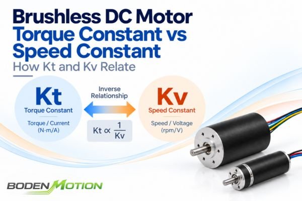
Changing the number of winding turns alters the motor's speed constant (Kv) and torque constant (Kt). Within the same motor family, a winding with more turns will typically have a lower Kv (slower speed per volt) and a higher Kt (more torque per amp).
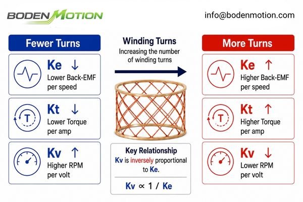
More turns in the coil create a stronger magnetic field interaction for a given current.4 This results in:
- Higher Back-EMF Constant (
Ke): The motor generates more back-EMF voltage for every RPM of rotation. - Higher Torque Constant (
Kt): The motor produces more torque for every amp of current supplied. - Lower Speed Constant (
Kv): SinceKvis inversely proportional toKe, the motor's no-load speed per volt is lower.
This interconnectedness is why you can't evaluate these parameters in isolation. The table below summarizes the typical tendencies for windings within the same motor family:
| Winding Characteristic | Lower-Voltage / High-Current | High-Voltage / Low-Current |
|---|---|---|
| Typical Turns | Fewer | More |
| Wire Diameter | Thicker | Thinner |
| Winding Resistance (R) | Lower | Higher |
| Speed Constant (Kv)5 | Higher | Lower |
| Torque Constant (Kt) | Lower (per Amp) | Higher (per Amp) |
| Current for Target Torque | Higher | Lower |
Real Example: Different Windings on the Same 16 mm Coreless Motor
The BDCM1625, a Ø16×25 mm coreless brushed DC motor, provides a useful real-world example of these trade-offs across its different winding configurations.
| BDCM1625 Winding | 6V | 12V | 24V |
|---|---|---|---|
| Terminal Resistance | 2.47 Ω | 9.23 Ω | 32.43 Ω |
| Speed Constant (Kv) | 1,633 rpm/V | 900 rpm/V | 458 rpm/V |
| Torque Constant (Kt) | 5.80 mN·m/A | 10.49 mN·m/A | 20.67 mN·m/A |
| Nominal Current | 0.50 A | 0.27 A | 0.15 A |
| Nominal Torque | 2.8 mN·m | 2.7 mN·m | 3.0 mN·m |
| Nominal Speed | 7,840 rpm | 8,640 rpm | 8,800 rpm |
This data illustrates the theory in practice:
- Resistance: As the nominal voltage increases from 6V to 24V, the terminal resistance increases dramatically from 2.47 Ω to 32.43 Ω.
- Kv/Kt: The higher-voltage windings have a significantly lower speed constant (
Kv) and a higher torque constant (Kt). The 24V version is not "faster per volt"; it's designed to reach its target speed using a higher voltage. - Current vs. Output: The three windings deliver comparable nominal torque within the same general nominal speed range, but they do so with very different voltage and current combinations.
How Voltage, Resistance, and Back EMF Determine Loaded Speed
Now, let's connect these winding parameters to what you actually see at the motor shaft: rotational speed under a real-world load.
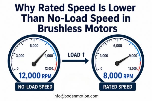
The motor's loaded speed is what's left after the supply voltage overcomes the internal resistive voltage drop (IR). As load increases, current increases, the IR drop grows, and the final speed decreases.
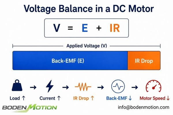
At a steady operating speed, the supplied voltage (V) must balance the back-EMF generated by rotation (E = Keω) and the voltage lost across the winding resistance (V_drop = IR).
Simplified Relationship:
V ≈ Keω + IR
By rearranging this, we can see what determines the speed (ω):
ω ≈ (V - IR) / Ke
This simple formula explains several key behaviors:
- Speed Droop Under Load6: When the mechanical load on the motor increases, it needs to draw more current (
I) to produce the required torque. This increases theIRdrop. With a fixed supply voltageV, less voltage is available for theKeωterm, so the speedωmust decrease. - Why Voltage Ratings Aren't a Speed Hierarchy7: A 24V winding is not automatically "faster" than a 12V one. The 24V winding has a lower
Kv(and higherKe). It's designed to reach a similar target speed by using a higher voltage but drawing lower current. The 12V winding, with its higherKv, achieves that same speed at a lower voltage but requires more current.
Low-Voltage/High-Current vs High-Voltage/Lower-Current Windings
So, which winding strategy is better? The answer depends entirely on your system's electrical platform and constraints.
These are different electrical configurations of the same motor platform, often providing overlapping mechanical capability while matching different voltage and current constraints.
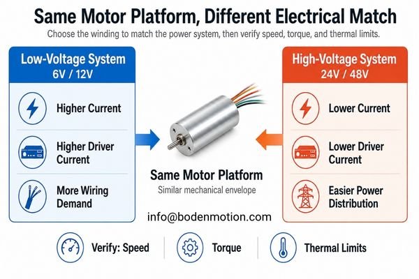
Windings for the same motor frame share the same basic mechanical envelope and similar frame-level magnetic and thermal constraints. However, the allowable continuous current, copper loss, efficiency, and specific thermal performance must still be verified for each winding.
| Selection Factor | Low-Voltage / Higher-Current Winding | High-Voltage / Lower-Current Winding |
|---|---|---|
| Supply Voltage | Typically matched to lower-voltage supplies (e.g., 3.7V, 6V, 12V) | Typically matched to higher-voltage supplies (e.g., 24V, 36V, 48V) |
| Current Draw | Typically higher for a comparable mechanical output | Typically lower for a comparable mechanical output |
| Driver Current Rating | Usually requires higher current capability | May allow a lower driver current rating |
| Wiring & Connectors | Higher current can increase voltage drop and conductor requirements | Lower current can reduce voltage drop and ease power distribution |
| Battery Systems | Often suited to lower-voltage, low-cell-count battery platforms | Often suited to higher-voltage, higher-cell-count battery platforms |
| Winding Resistance (R)8 | Typically lower | Typically higher |
| Speed Constant (Kv)9 | Typically higher | Typically lower |
| Torque Constant (Kt) | Typically lower (torque per amp) | Typically higher (torque per amp) |
The key takeaway is that you choose the winding that best fits your power supply and driver. If you have a 24V system with strict current limits, a 24V winding designed for lower operating current is usually a suitable starting point, provided the required loaded speed, torque, and thermal limits are also satisfied.
What OEM Buyers Should Provide Before Choosing a Coreless Motor Winding
To avoid cycles of trial-and-error, a clear set of requirements is essential. Asking for "a 24V motor" is not enough information to ensure success.
OEMs should provide the complete operating point, including voltage range, current limits, target speed under load, and torque requirements, to allow for proper winding selection.
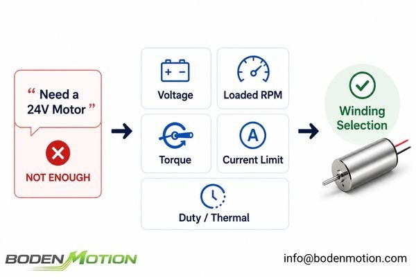
The more useful inquiry moves from "Do you have a 24V version?" to "We have a 24V bus, need X RPM at Y torque, and the driver current must stay below Z amps."
Here’s a checklist of what to provide:
- Power Supply:
- Nominal, minimum, and maximum supply voltage
- Battery or regulated DC supply
- Driver Limits:
- Continuous and peak current limits
- Mechanical Requirements:
- Target no-load speed (for reference)
- Required loaded speed and the corresponding continuous torque10
- Peak torque and its duration/duty cycle
- System Constraints:
- Maximum acceptable current draw
- Wire gauge or connector limitations
- Physical motor dimensions
- Thermal Conditions:
- Ambient temperature and cooling method (e.g., passive, heatsink)
With this data, we at BODENMOTION can effectively compare different winding options and recommend a solution that not only performs correctly but also operates reliably within your system's electrical and thermal boundaries.
How to Choose the Right Winding for Your Voltage and Current Limits
The selection process should be a systematic matching of your application needs to the motor's winding characteristics, not a guess based on voltage. As with broader DC motor selection, the electrical platform, operating point, driver limits, and thermal conditions should be evaluated together.
Choose the winding by starting with your electrical platform and mechanical operating point, then verifying that the motor's current draw and thermal performance are within your system's limits.
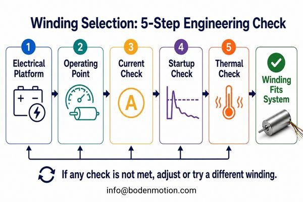
Here is a practical, step-by-step approach for choosing the right winding:
Step 1: Define Your Electrical Platform
Start with your power source. What is your nominal voltage, what is the operating range (e.g., a battery's discharge curve), and what is the maximum current your supply and driver can handle?
Step 2: Define Your Mechanical Operating Point
Specify the speed you need under load. A no-load RPM value is useful, but the speed at your continuous working torque is the most critical parameter.
Step 3: Check Current Demands
For a brushed DC motor, a useful first-pass approximation is I ≈ I₀ + T / Kt, where I₀ is the no-load current and T is the load torque. For a BLDC motor, use the manufacturer’s specified torque constant and current definition together with the actual drive configuration. Compare this estimated current to your driver's continuous and peak ratings.
Step 4: Evaluate Startup Conditions
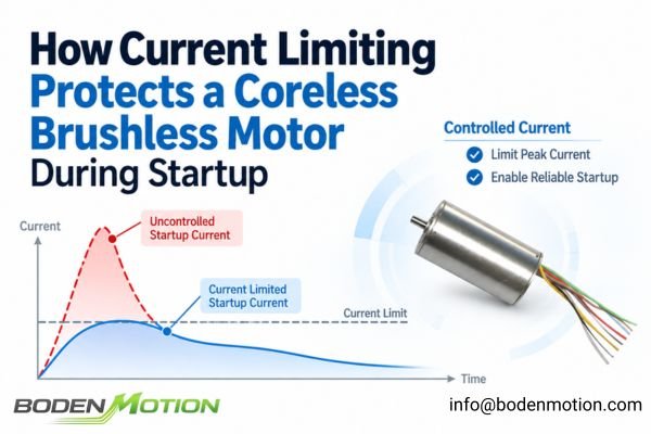
A low-resistance winding can draw very high current at startup11. Ensure your power supply can handle this inrush current without significant voltage sag and that your driver's peak current limit is not exceeded.
Step 5: Assess Thermal Performance
For a brushed DC motor, estimate winding copper loss using P_loss ≈ I_rms²R12 based on the load profile and duty cycle. For a BLDC motor, use the appropriate RMS phase current and phase resistance defined by the motor winding and drive configuration. Verify that the motor will be able to dissipate this heat in your application's environment without exceeding its maximum winding temperature.
This table can help guide your initial evaluation:
| If Your System Has... | Winding Direction to Evaluate |
|---|---|
| A low-voltage battery platform | A lower-voltage winding, which typically has a higher Kv. |
| A strict driver current limit | A higher-voltage winding to reduce operating current. |
| Long cables or thin wiring | A higher-voltage, lower-current option to minimize IR drop. |
| A need for very high RPM at a limited voltage | A winding with a higher Kv (typically a lower-voltage version). |
| A high continuous load | Selection must be based on thermal analysis, not voltage alone. |
Ultimately, the best winding is the one that allows the motor to achieve the required mechanical performance while staying comfortably within the electrical and thermal boundaries of your entire system.
Conclusion
Winding resistance is part of an interconnected motor design: changes in winding turns and wire size affect resistance, Kv, Kt, current draw, and thermal behavior. A higher-voltage winding is not inherently better—it is simply configured for a different voltage and current range.
For OEM applications, the right winding should be selected by matching the supply voltage, loaded speed, torque, current limits, and thermal conditions to the motor platform. Share your operating point with us at info@bodenmotion.com, and our engineering team can help evaluate the most suitable winding option.
FAQ
Q1: Why do 12V and 24V versions of the same coreless motor have different resistance?
Different voltage versions typically use a different number of winding turns and wire diameters to fit within the same physical space. A 24V version often uses more turns of thinner wire, resulting in higher resistance than a 12V version.
Q2: Does a higher-resistance winding use less current?
For a comparable power output, a higher-resistance winding designed for a higher voltage system typically draws less current. However, the actual current depends on the load torque, back-EMF, and the motor's torque constant (Kt).
Q3: Does a 24V coreless motor run faster than a 12V motor?
Not necessarily. A 24V winding usually has a lower speed constant (Kv), meaning it runs slower per volt. It is designed to achieve a target operational speed at a 24V supply, which may be similar to the speed a 12V motor achieves at a 12V supply.
Q4: Does higher winding resistance mean more motor heat?
Not by itself. Heat from copper losses is calculated by I²R. A higher-resistance (R) winding designed for a higher-voltage system also operates at a lower current (I). Depending on the operating point, the total I²R loss can be comparable or even lower than a low-resistance winding.
Q5: What information should OEM buyers provide when choosing a motor winding?
Provide your available voltage range, driver current limits, target loaded speed, continuous and peak torque, duty cycle, physical constraints, and thermal environment. This allows engineers to match a winding to your specific operating point.
ECE252 Lesson 19, University of Louisville. The lesson relates applied voltage, back EMF, armature resistance, current, speed, and torque in a DC motor, providing the electrical basis for matching motor requirements to available voltage, speed, torque, and current constraints. ↩
Temperature Coefficient of Resistance, HyperPhysics, Georgia State University. Copper has a positive temperature coefficient of resistance, so the resistance of a copper winding increases as its temperature rises. ↩
The DC Motor, Rice University ECE. The motor torque relationship T = KtI shows that, for a given required torque, a lower torque constant requires a higher armature current. ↩
The Feynman Lectures on Physics, Volume II, Chapter 16. The motor discussion explains that using more turns in the coil can produce greater torque for a given current because more current-carrying conductors interact with the magnetic field. ↩
Motor Constants KV, Kt, Ke, Km Explained, Source Robotics. The article defines Kv as the motor speed constant in rpm per volt and explains how winding turns influence Kv, with more turns generally corresponding to a lower speed constant. ↩
Development of a DC Motor Model and an Actuator Efficiency Model, Idaho National Engineering and Environmental Laboratory. The DC motor model relates torque, armature current, resistance, back EMF, and speed, while its speed-torque curves show motor speed decreasing as load torque increases. ↩
Motor Constants, Wikipedia. The article defines Kv as speed per volt and explains that Kv is affected by winding selection and the number of winding turns, showing why nominal voltage alone does not form a simple hierarchy of motor speed. ↩
ECE252 Lesson 19, University of Louisville. The lesson identifies armature resistance as an electrical parameter of the motor winding and shows how it influences armature current together with applied voltage and back EMF. ↩
Motors and Actuators, MIT Center for Bits and Atoms. The course material defines Kv as motor speed per volt and explains that winding style and winding turns determine the motor constant, with more turns generally resulting in a lower Kv. ↩
Motor Application Guide, Malloy Electric. The guide treats torque and speed as paired mechanical requirements for motor sizing and distinguishes continuous-duty operation from short-time and intermittent duty. ↩
Inrush Current, Wikipedia. At startup, a brushed motor has little or no back EMF and initially presents essentially its winding resistance, so a low-resistance winding can allow a high starting current unless the system limits it. ↩
AC Losses Calculation of Parallel Multi-Strand Flat Wire Windings for Automotive Drive Motor, IET Electric Power Applications. The study states that winding DC loss is proportional to the square of the RMS current and relates this loss to winding resistance and conductor conductivity, supporting the use of I_rms²R as a first-pass copper-loss estimate. ↩