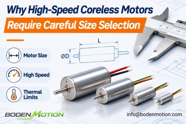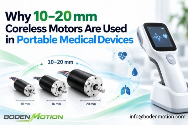
Designing motion systems for portable medical equipment requires engineers to balance limited installation space, low device weight, responsive motion, acoustic noise, vibration, thermal behavior, and battery constraints. This is why compact coreless motors, particularly those in the 10–20 mm diameter range, are frequently evaluated for handheld instruments, miniature pumps, diagnostic equipment, and other portable medical systems.
The value of 10–20 mm coreless motors comes from the balance they can provide between compact packaging, responsive motion, smooth torque behavior, and usable mechanical output. However, this diameter class is a practical engineering range rather than a formal medical standard; the correct motor must still be selected from the complete mechanical, electrical, thermal, lifetime, and environmental requirements of the device.
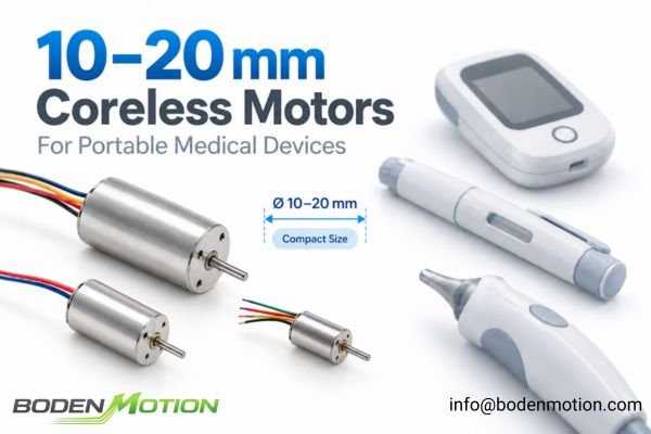
Motor diameter is therefore only one part of the selection problem. The same device may also impose limits on axial length, operating voltage, allowable temperature rise, acoustic behavior, control architecture, and expected service life.
Why the 10–20 mm Size Range Fits Portable Medical Device Architectures
Portable medical devices often place strict limits on radial space, axial length, and total assembly weight. A motor must fit within the available housing while still providing sufficient mechanical output and thermal margin for the required operating cycle.
Motor diameter is often one of the first packaging constraints in a portable medical device, but it must be evaluated together with available length, torque requirements, duty cycle, bearing capability, and thermal conditions rather than treated as an isolated selection parameter.
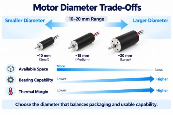
Smaller diameters favor compact packaging and lower motor mass, while larger diameters generally provide more room for mechanical and thermal capability. The useful design range depends on how these constraints interact with the available axial length and the actual operating requirements.
For many handheld and portable mechanisms, the 10–20 mm range therefore represents a practical compromise between miniaturization and usable mechanical capability.
Typical applications may include:
- Handheld diagnostic instruments
- Compact drug-delivery mechanisms
- Portable laboratory equipment
- Miniature diaphragm or peristaltic pump drives
- Dental and surgical hand tools
- Small positioning and adjustment mechanisms
The exact motor size should still be determined by the complete operating requirement rather than by the application category alone.
Why Low Rotor Inertia Matters in Portable Medical Motion Systems
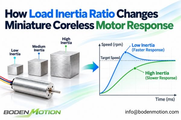
Many portable medical mechanisms do not operate at a constant speed. They repeatedly start, stop, accelerate, decelerate, or reverse direction during dispensing, positioning, pumping, or tool operation.
Low rotor inertia can improve dynamic response because less motor torque is required to accelerate the rotor itself. This advantage is especially direct in brushed coreless motors, where the lightweight self-supporting winding forms part of the rotating armature. Brushless coreless motors—often described as slotless because the stator winding is not placed in conventional iron teeth and slots—can also be designed with very low rotor inertia, but their inertia depends more directly on the permanent-magnet rotor geometry and overall mechanical construction.
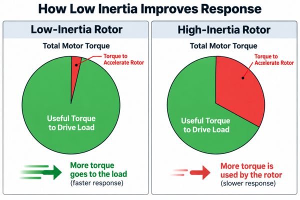
When rotor inertia is low, more of the available torque can be used to accelerate the actual load rather than the motor's own rotating structure.1 This can help shorten response and settling times in mechanisms that operate through frequent motion cycles.
For example, a dispensing mechanism may need to accelerate quickly, deliver a controlled amount of fluid, stop accurately, and then repeat the process many times. A positioning mechanism may need rapid direction changes without excessive settling delay.
In a handheld tool, a low-inertia motor design can also improve perceived responsiveness because the rotating system reacts more quickly to changes in the commanded operating point.
For highly intermittent motion profiles, lower rotor inertia reduces the kinetic energy that must be added during acceleration and managed during deceleration. However, the actual effect on battery runtime depends on the complete duty cycle, mechanical load, driver strategy, operating efficiency, and whether energy can be recovered during deceleration.
Low inertia should therefore be treated primarily as a dynamic-performance characteristic rather than as a guarantee of lower system power consumption.2
How Coreless Motors Help Reduce Vibration and Motion Disturbance
Vibration can affect user comfort, measurement stability, positioning accuracy, fluid delivery, and the behavior of sensitive optical or sensing components inside portable medical equipment.
In typical permanent-magnet coreless or slotless designs, the absence of conventional slotted iron teeth largely eliminates the cogging torque associated with tooth-slot interaction. This can support smoother electromagnetic behavior, but it does not eliminate commutation-related torque ripple, rotor imbalance, bearing vibration, or other system-level disturbances.
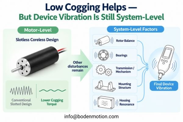
The final vibration signature can be affected by several sources:
- Rotor Balance3: Uneven rotating mass can generate vibration that becomes increasingly significant as speed rises.
- Bearings: Bearing quality, lubrication, preload, installation, and wear can influence mechanical vibration.
- Commutation: Brushed commutation and electronic BLDC commutation can introduce different forms of torque disturbance.
- Transmission: Gearboxes, couplings, cams, pump mechanisms, or eccentric loads can introduce additional vibration.
- Mounting: A flexible or poorly supported motor mount may amplify vibration rather than isolate it.
- Housing Structure4: Lightweight plastic housings can have resonant modes that amplify relatively small excitation forces.
This distinction is important in medical equipment because low cogging at the motor level does not automatically guarantee a low-vibration device.
For handheld systems, vibration should preferably be evaluated through the actual housing and mechanism. For diagnostic or optical equipment, testing should also consider whether vibration affects sensing stability, alignment, or measurement repeatability.
The motor can reduce one source of disturbance, but device-level validation is still required.
Why Medical Device Noise Must Be Evaluated at the System Level
Portable medical equipment often operates close to patients, clinicians, technicians, or laboratory personnel. Acoustic behavior can therefore influence both user experience and the perceived quality of the final product.
A motor's acoustic performance cannot be evaluated independently from the system around it. The final noise level depends on the motor operating point, bearings, commutation, transmission mechanism, mounting stiffness, and the acoustic response of the device housing.
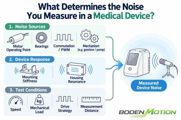
Motor-related sources may include:
- Bearing noise
- Brush-commutator interaction in brushed motors
- Electronic commutation in brushless motors
- PWM-related excitation
- Rotor imbalance
- Shaft or coupling alignment
The surrounding mechanism may add additional sources. A gearbox can generate gear-mesh noise5, while pumps, cams, fans, or reciprocating mechanisms can introduce their own periodic excitation.
The device enclosure can then amplify these disturbances. A lightweight plastic cover, for example, may behave like a soundboard if one of its structural resonances is excited by the motor or transmission.
For this reason, describing a motor simply as "quiet" is not enough for an OEM specification.
Noise testing should ideally define:
- Motor speed
- Mechanical load
- Drive strategy
- Mounting condition
- Measurement distance
- Device configuration
- Relevant duty cycle
The most meaningful acoustic result is usually obtained from the assembled device operating under realistic conditions.
10 mm vs. 12 mm vs. 16 mm vs. 20 mm: What Changes as Motor Size Increases?
Once the available design space has been narrowed to approximately 10–20 mm, diameter becomes useful for comparing how packaging, mechanical capability, thermal margin, and dynamic behavior may shift between motor classes.
Under otherwise comparable motor designs, increasing diameter generally allows more electromagnetic working volume, larger bearings, and greater thermal capacity, but it can also increase package size, motor mass, and rotating inertia. The correct diameter is therefore the one that provides sufficient performance margin without creating unnecessary packaging or dynamic penalties.
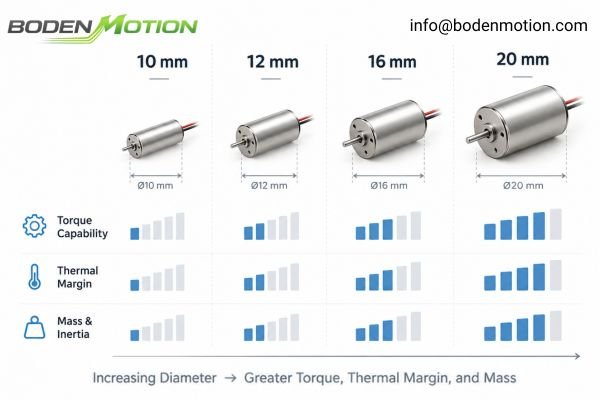
Diameter alone does not determine motor capability. Motor length, winding design, voltage, magnetic circuit, speed, commutation architecture, and cooling conditions can significantly change the result.6
For example, a longer 12 mm motor may provide more usable output than a shorter 16 mm motor under some operating conditions. Likewise, two motors of the same diameter can behave very differently if they use different windings, magnetic designs, or thermal paths.
The following table should therefore be treated as a general design guide rather than a fixed performance classification.
| Diameter Class | Typical Design Strength | Main Trade-Off |
|---|---|---|
| ~10 mm | Extremely compact and lightweight | Tight continuous torque and thermal margin |
| ~12 mm | Compact with more usable mechanical capability | Still sensitive to duty cycle and thermal conditions |
| ~16 mm | Strong balance of output, bearings, and thermal margin | Larger package and higher rotating mass |
| ~20 mm | Greater mechanical and thermal capability | More installation volume and weight required |
The correct engineering question is therefore not simply whether a 10 mm, 12 mm, 16 mm, or 20 mm motor is "better."
It is whether the complete motor configuration can provide the required torque-speed operating points, lifetime, thermal margin, and dynamic behavior within the available device envelope.
Brushed vs. Brushless Coreless Motors for Portable Medical Devices
Diameter is only one design decision. Within a similar packaging range, an OEM may also need to decide between brushed and brushless coreless motor architectures based on the electrical system and expected operating conditions.
The choice between brushed and brushless coreless motors is a system-level trade-off involving drive complexity, lifetime, acoustic behavior, speed range, available electronics, control requirements, and cost. Neither architecture is universally better for portable medical devices.
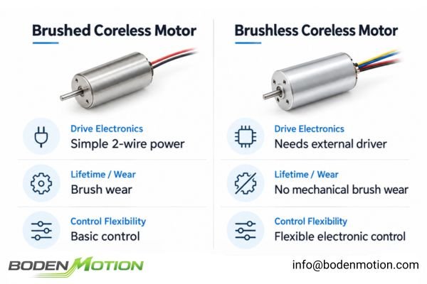
The relationship between motor diameter and commutation architecture is not fixed.
For example, within the BODENMOTION coreless motor platform, the BDCL1020 uses a brushless architecture in a compact Ø10 × 20 mm package, while the BDCM1219 uses precious-metal brushed commutation in an Ø12 × 19 mm package. A larger Ø16 × 26 mm BDCB1626 platform uses graphite brushes.
These examples illustrate that diameter and commutation method are separate design variables. They should be treated as engineering references rather than universal recommendations for medical applications, since final suitability depends on the required speed, torque, duty cycle, lifetime, thermal conditions, environment, and device-level validation7.
Brushed Coreless Motors
Potential strengths include:
- Simple two-wire electrical operation
- Relatively straightforward drive electronics
- Compact control architecture
- Practical integration where sophisticated speed control is not required
Important considerations include:
- Brush and commutator wear
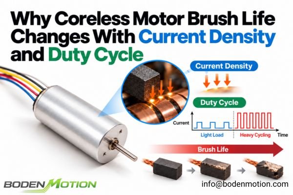
- Lifetime dependence on speed, current, load, and duty cycle
- Electrical commutation noise
- Possible acoustic effects from brush interaction
- Performance changes as the brush system wears
Brushed motors can therefore remain practical in compact or intermittent-duty mechanisms where drive simplicity is important and the required lifetime is compatible with the brush system.
Brushless Coreless Motors
Potential strengths include:
- No mechanical brush wear
- Flexible electronic speed and torque control
- Potential for extended service life when correctly designed and operated
Important considerations include:
- Requirement for an electronic driver
- Driver size and cost
- Commutation strategy
- PWM frequency
- Control integration
- Electrical and acoustic interaction with the complete system
Brushless architecture removes mechanical brush wear, but it does not eliminate every source of noise, vibration, or electrical complexity.
The OEM decision should therefore be made from the complete operating requirement rather than from a general assumption that one commutation architecture is always superior
How Medical OEM Engineers Should Select a Coreless Motor
Selecting a miniature motor for a portable medical device should begin with a complete definition of the system rather than with a preferred diameter, voltage, or motor model.
The correct motor is identified by matching the mechanical envelope, electrical platform, torque-speed requirements, duty cycle, NVH targets, thermal limits, lifetime expectations, and environmental conditions of the device. Motor selection should therefore be treated as part of the complete medical-device motion system rather than as an isolated component decision.
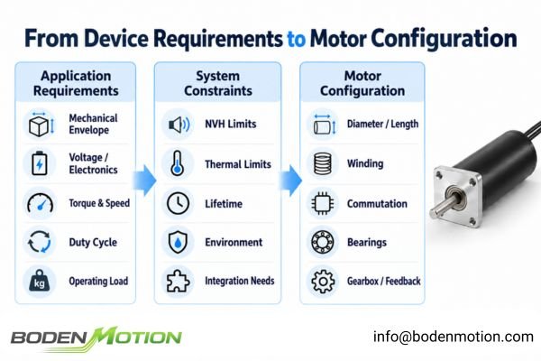
A structured definition of these requirements gives the motor supplier enough information to evaluate diameter, length, winding, commutation architecture, bearing system, gearbox, feedback, and other configuration choices.
Define the Mechanical, Electrical, and Operating Requirements
The first step is to define both the physical limits of the device and the actual operating profile of the motor.
- Maximum motor diameter, length, and weight
- Shaft and mounting requirements
- Supply voltage and driver current capability
- Target speed
- Continuous and peak torque
- Duty cycle and operating time per cycle
- Start-stop frequency and acceleration requirements
- Direction reversals and load inertia
- Expected lifetime in operating hours or cycles
The torque-speed operating point is particularly important. A motor that physically fits the available envelope may still be unsuitable if it cannot provide the required torque without excessive current or temperature rise.8 Likewise, a motor selected only from a nominal torque value may behave very differently when exposed to repeated acceleration, frequent starting, or long continuous operating periods.
Define NVH, Thermal, Lifetime, and Integration Conditions
OEM engineers should also define the system-level and environmental conditions that may limit motor selection:
- Device-level acoustic noise and vibration targets
- Maximum motor or winding temperature
- Maximum allowable device temperature rise
- Ambient and storage temperature
- Cooling conditions
- Required service life
- Exposure to moisture or cleaning agents
- Sterilization exposure
- Encoder or gearbox requirements
- Traceability, material, or documentation requirements
Motor integration for a medical device application should therefore be evaluated beyond basic torque and speed requirements. Packaging, thermal behavior, acoustic performance, environmental exposure, and documentation requirements can all influence whether a motor is suitable for the final system.
Use in a medical device does not automatically make a motor "medical grade." Material compatibility, sterilization exposure, lifetime, documentation, traceability, and device-level validation requirements must be defined for the specific application.
Similarly, a motor should not be described as sterilizable or autoclavable unless its materials and complete construction have been specifically designed and validated for the intended sterilization process.
Translate Device Requirements into Motor Selection Priorities
Once the application requirements are defined, they can be translated into practical motor-selection priorities.
| Device Requirement | Motor Selection Priority |
|---|---|
| Very small handheld enclosure | Diameter + length + mass + integration space |
| Quiet operation | Bearings + commutation + drive strategy + mounting / housing |
| Low vibration | Rotor balance + low-cogging electromagnetic design + mechanism / mounting |
| Fast dynamic response | Rotor inertia + peak torque / current margin |
| Low-speed precision motion | Torque smoothness + feedback resolution + current control |
| Battery-powered operation | Efficiency across the actual duty cycle + driver efficiency |
| Long continuous runtime | Continuous torque capability + thermal path + allowable temperature rise |
| Sterilization exposure | Exposed materials + process compatibility + application-specific validation |
The final selection should therefore be based on the complete operating profile. Diameter provides a packaging boundary, but successful medical-device integration depends on how the motor performs as part of the complete mechanical and electrical system.
Conclusion
Coreless motors in the 10–20 mm diameter range are frequently considered for portable medical devices because this size class can provide a practical balance of compact packaging, responsive motion, smooth electromagnetic behavior, and usable mechanical output. The range should be treated as an engineering design space rather than a medical industry standard, and the appropriate diameter and motor architecture depend on the complete device requirements.
The final motor should be selected by evaluating Envelope + Torque + Speed + Duty Cycle + NVH + Thermal Margin + Lifetime + Environment + Control Architecture as one system. Defining these requirements clearly allows the motor configuration to be matched to the actual application rather than selecting from diameter or motor type alone. For OEM motor evaluation or customization, contact the BODENMOTION engineering team at info@bodenmotion.com.
FAQ
Q1: Why are coreless motors used in portable medical devices?
Coreless motors are frequently considered because their compact construction, smooth electromagnetic behavior, and potential for responsive dynamic performance can support miniature medical motion systems where space, weight, vibration, and response time are important.
In brushed coreless motors, the lightweight rotating winding can directly contribute to low rotor inertia. Brushless coreless or slotless motors can also achieve low inertia, but this depends on the specific permanent-magnet rotor design.
Actual efficiency, noise, temperature rise, and lifetime still depend on the motor design and its real operating conditions.
Q2: Are 10–20 mm coreless motors a medical industry standard?
No. The 10–20 mm diameter range is a useful design space for many portable medical mechanisms, but it is not a formal medical standard.
The correct diameter depends on the available installation space, motor length, torque-speed requirements, duty cycle, thermal margin, lifetime, and integration conditions.
Q3: Are coreless motors quieter than conventional motors?
In typical permanent-magnet coreless or slotless designs, the absence of conventional slotted iron teeth largely eliminates the cogging torque associated with tooth-slot interaction, which may support smoother electromagnetic behavior.
However, this does not eliminate commutation-related torque ripple or mechanical noise. Final device-level noise also depends on bearings, speed, load, gearbox or pump mechanisms, mounting, and housing resonance. Acoustic performance should therefore be evaluated in the assembled device.
Q4: Should a medical device use a brushed or brushless coreless motor?
It depends on the system requirements.
Brushed motors can be practical where simple drive electronics, compact control, or intermittent operation are priorities. Brushless motors eliminate mechanical brush wear and are often considered where long operating life, frequent cycling, high-speed operation, or more flexible electronic control is important.
The final choice should also consider cost, available driver electronics, acoustic behavior, duty cycle, speed, and required lifetime.
Q5: Can coreless motors be used in sterilized medical equipment?
Potentially, but compatibility must be evaluated for the specific sterilization process and motor construction.
A motor located inside a sealed device may never be directly exposed to sterilization, while another application may expose motor materials, bearings, adhesives, lubricants, insulation, or electronics to autoclave, EtO, gamma, or other processes.
Use in a medical device does not automatically mean that the motor itself is sterilizable. Direct sterilization exposure requires appropriate material selection and application-specific validation.
Linear Motion Tips’ “Inertia Matching: Why Perfect Isn't Always Best” explains that higher motor inertia consumes more of the available torque during acceleration, supporting the conclusion that a lower-inertia rotor leaves a greater share of torque available to accelerate the driven load. ↩
Portescap’s “Motor Selection Basics: Inertia and Power and Torque Requirements” explains that lower rotor inertia improves acceleration, deceleration, and dynamic response, while overall power and energy requirements still depend on the load, acceleration profile, friction, transmission, and complete motion system. ↩
Texas A&M Turbomachinery Laboratory’s “Rotor Balancing Tutorial” identifies rotor unbalance as a common cause of synchronous vibration and shows that the force generated by an unbalanced rotating mass increases with the square of rotational speed. ↩
Missouri University of Science and Technology’s “Soil and Structure Vibrations from Construction and Industrial Sources” shows that structural vibration can be amplified when excitation approaches a structure’s natural frequency, supporting the general resonance mechanism by which relatively small vibration inputs can produce larger structural responses. ↩
Gear Solutions’ “Investigating Epicyclic Gear Whine” explains that loaded gear meshes can generate transmission-error excitation that propagates through gears, shafts, bearings, and the housing and can radiate as audible gear whine. ↩
“Electric Motor Modeling, Analysis, and Design for E-Mobility Applications: A State of the Art” reviews how motor dimensions, winding arrangement, magnetic design and materials, operating speed, electrical operating conditions, and thermal design can materially affect torque, efficiency, losses, temperature, and other motor performance characteristics. ↩
Electronic Product Design & Test’s “Key Medical Device Design Considerations – Selecting a Suitable Drive System” identifies torque requirements, operating time, start-stop frequency, expected lifespan, available space, materials, and application-specific environmental exposure as important considerations when selecting a drive system for medical equipment. ↩
The Ansys Motor-CAD User Guide’s “Thermal Envelope” describes how usable motor torque and power can be constrained by current, electromagnetic capability, and winding-temperature limits, supporting the conclusion that satisfying the mechanical packaging requirement alone does not guarantee a feasible operating point. ↩