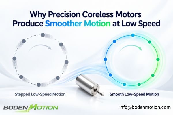
Precision coreless motors are often specified for applications requiring exceptionally smooth low-speed motion because their architecture structurally minimizes cogging torque, a primary source of low-speed disturbance in conventional motors. By removing or avoiding the conventional toothed iron structure responsible for slot-related magnetic attraction, periodic torque variation is greatly reduced.
However, low cogging does not automatically guarantee smooth low-speed motion. Commutation effects, driver current ripple, mechanical friction, and feedback quality can still limit performance, so the more useful engineering question is not simply whether the motor is coreless, but whether the complete motor-driver-feedback-mechanical system can control the disturbances that remain at the required minimum speed.
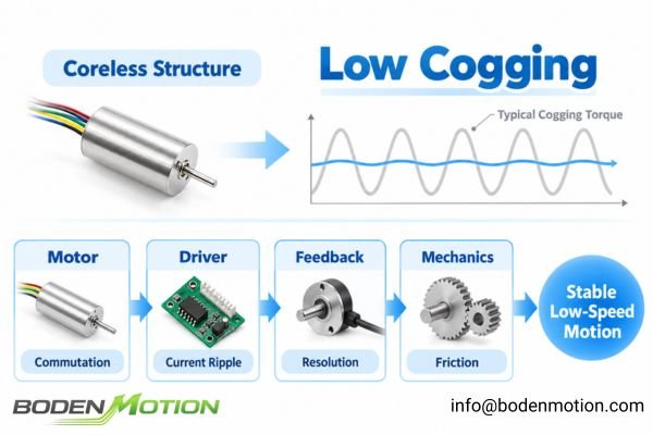
Coreless construction therefore provides the physical foundation for smoother motion, but the sources that ultimately determine minimum stable speed extend beyond the motor structure itself.
How Coreless Architecture Reduces Cogging Torque
In a conventional motor with a slotted iron core, permanent magnets interact with iron teeth as the rotor turns. This creates a position-dependent torque variation, known as cogging, even when no current is applied.
Coreless and slotless architectures reduce this disturbance by avoiding the conventional tooth-slot magnetic interaction, removing one of the main structural causes of jerky motion and speed variation at low speed.
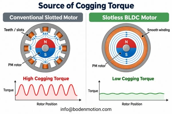
The physical implementation differs between brushed and brushless designs, so the term "coreless" should not imply that both motor architectures use the same rotating structure.
- In a brushed coreless motor, the winding is a self-supporting, rotating cup with no iron armature core.
- In a coreless/slotless BLDC motor, the stator winding is formed without conventional iron teeth, creating a smooth cylindrical air-gap structure around the rotor magnets.
In both cases, avoiding conventional tooth-slot interaction greatly reduces periodic reluctance variation experienced by the rotor magnets1. The motor therefore begins with a lower structural torque disturbance before the controller attempts to regulate speed or position2.
How Rotor Dynamics Affect Controllability
The dynamic characteristics of coreless motors also contribute to their suitability for precision motion, although the specific advantage differs between brushed and brushless architectures.
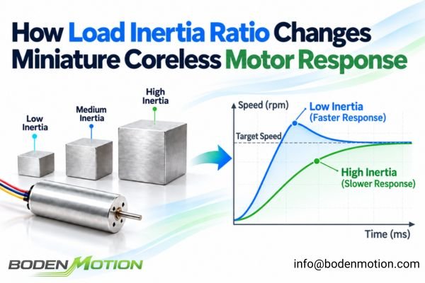
Low rotor inertia does not directly eliminate torque ripple, but where it is present—particularly in brushed coreless cup-winding designs—it allows the control system to make faster corrections during acceleration, deceleration, positioning, and direction reversal.
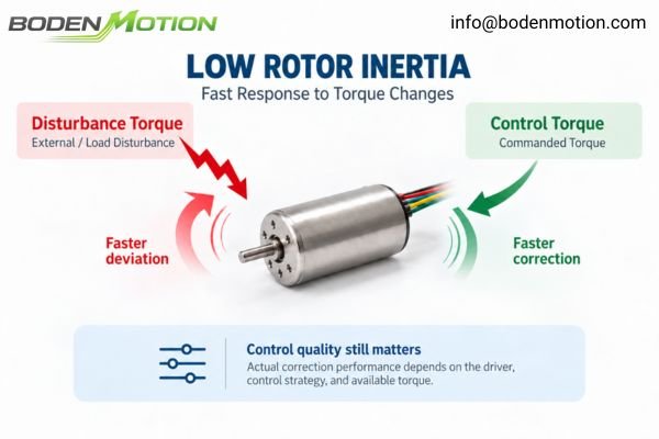
In a typical brushed coreless motor, the rotating winding is a hollow, lightweight cup. This produces very low rotating mass and allows the motor to respond rapidly to changes in commanded torque.
In a coreless BLDC motor, by contrast, the rotor is formed by the permanent-magnet assembly. Its inertia depends on factors such as magnet geometry, rotor diameter, material, and mass, and is not necessarily lower than every conventional motor rotor.
The important distinction is that low inertia improves dynamic controllability, while reduced cogging improves the motor's structural smoothness. They are related advantages, but they are not the same mechanism.
A low-inertia system can also respond more readily to unwanted disturbances such as current ripple, controller noise, or sudden load changes. Driver and control quality therefore remain important even when rotor inertia is very low.
What Still Causes Torque Ripple in a Coreless Motor?
Even after cogging has been structurally minimized, electromagnetic, mechanical, and control-related disturbances can still affect low-speed smoothness.
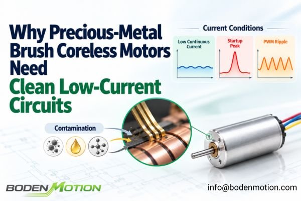
One important trade-off is that many small coreless and ironless motors have relatively low winding inductance. This supports fast electrical response, but it can also make the motor more sensitive to PWM frequency and current-control quality, allowing current ripple to appear directly as torque ripple.
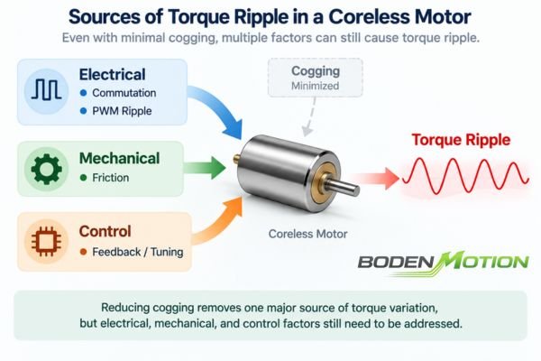
Reducing cogging therefore removes one major structural disturbance, but it does not remove the electrical, mechanical, and control-related sources of torque variation that remain in the complete drive system.
Key remaining ripple sources include:
-
Electromagnetic Effects:
- Brushed Commutation: Physical transition of the brushes between commutator segments, along with contact resistance and brush-pressure variations.
- BLDC Commutation: Imperfections in electronic commutation timing and current waveform shaping.
- PWM Current Ripple: High-frequency ripple in motor current generated by the drive electronics.
-
Mechanical Effects:
- Bearing friction, including static and running friction.
- Friction from shaft seals, gearboxes, couplings, or the load itself.
- Mechanical misalignment, backlash, or load eccentricity.
-
Control Effects:
- Limited feedback resolution.
- Current-sampling noise and control-loop bandwidth.
- Speed-loop and current-loop tuning.
This is why an ironless motor can have extremely low cogging and still show visible speed ripple if its driver, mechanical load, or feedback system is poorly matched.
Brushed Coreless vs. Coreless BLDC at Low Speed
Both brushed and brushless coreless architectures can achieve excellent low-speed performance, but the disturbances that limit their smoothness are different.
The ironless structure benefits both architectures, but brushed motors depend more on mechanical commutation quality, while BLDC motors depend more heavily on electronic commutation, current regulation, and rotor-position feedback.
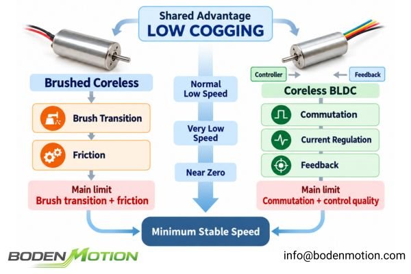
This difference becomes especially important as the required operating speed approaches the lower limit of the drive system.
| Low-Speed Factor | Brushed Coreless Motor | Coreless BLDC Motor |
|---|---|---|
| Cogging Torque | Very low / structurally minimized | Very low / structurally minimized |
| Rotor Inertia | Typically very low due to rotating cup winding | Depends on rotor magnet geometry and mass |
| Commutation | Mechanical brushes | Electronic |
| Main Ripple Source | Brush/commutator transition and friction | Commutation timing and current ripple |
| Control Complexity | Lower | Higher |
| Low-Speed Optimization | Contact quality, drive method, feedback | Current loop, feedback, commutation strategy |
A brushed coreless motor can operate from a relatively simple DC drive because commutation is mechanical, although precise low-speed regulation still benefits from closed-loop feedback. At very low speed, torque variation and friction at the brush-commutator interface can become increasingly visible.
A coreless BLDC motor eliminates brushes and their associated friction and wear3. Its low-speed behavior, however, depends heavily on electronic commutation quality, current-loop stability, and available rotor-position information.
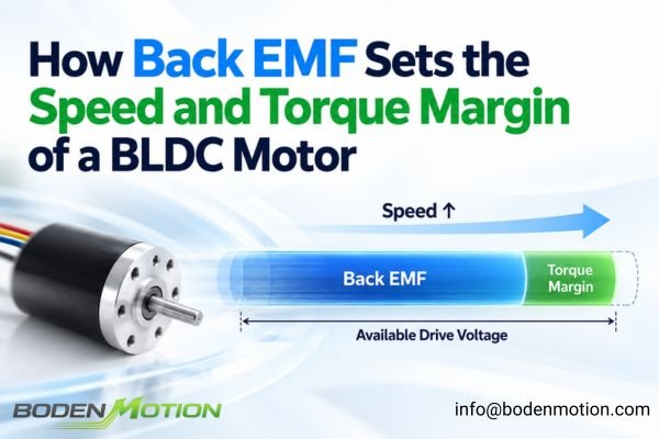
Conventional back-EMF-based sensorless control becomes more difficult at very low or near-zero speed because the available back-EMF signal becomes weak4. Hall-sensored configurations can provide more defined startup and low-speed commutation than basic back-EMF sensorless control, while high-resolution encoder feedback is generally more suitable when precise low-speed velocity regulation or positioning is required.
Why Friction Becomes More Important at Low Speed
Near zero speed, nonlinear mechanical disturbances such as static friction become increasingly visible and can become a major limitation on smooth motion.
Low cogging does not remove mechanical friction. The motor must still overcome breakaway torque, and the transition between static and dynamic friction can create stick-slip that limits minimum stable speed even when electromagnetic cogging is very low.
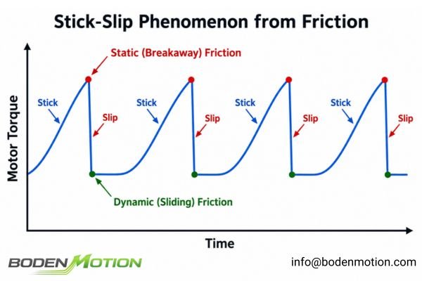
Before motion begins, motor torque must overcome the breakaway friction of the complete mechanical system, including bearings, seals, transmission components, and the load.
Once movement begins, friction may fall to a lower dynamic level. The difference between static and dynamic friction is a major mechanism behind stick-slip, where the system resists motion and then moves suddenly after breakaway torque is exceeded.
The severity of this behavior also depends on:
- Mechanical compliance.
- Structural stiffness.
- Damping.
- Gearbox behavior.
- Backlash.
- Controller response.
As a result, even a motor with extremely low cogging can exhibit poor low-speed smoothness when connected to a mechanical system with significant friction, backlash, or compliance.
How Feedback and Driver Control Affect Minimum Stable Speed
A motor's physical smoothness provides the foundation for low-speed operation, but the drive and feedback system determine how much of that potential can actually be used.
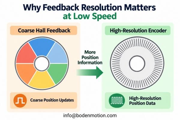
At very low speed, torque quality is strongly dependent on current-control quality, while stable velocity regulation depends on having enough position information to detect and correct small changes in rotor motion.
A stable current loop is important for producing consistent torque while counteracting friction and other disturbances. PWM ripple, current-sampling noise, current-loop bandwidth, and the match between driver characteristics and motor inductance can all affect the resulting torque waveform.
Feedback resolution is equally important.
-
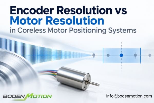
Encoders: At low speed, an encoder with insufficient resolution provides relatively sparse position updates, making accurate velocity estimation more difficult. This can lead to hunting or oscillation around the target speed. Effective feedback quality also depends on signal integrity, interpolation, transmission backlash, and mechanical compliance—not just nominal CPR.
-
Hall Sensors: Standard three-Hall commutation provides relatively coarse rotor-position information compared with a high-resolution encoder. Hall feedback is well suited to commutation and defined rotor-position sectors, but it is generally too coarse for high-precision low-speed velocity regulation by itself.
Speed-loop tuning introduces another trade-off. An aggressive loop can correct speed errors quickly but may amplify oscillation, noise, or mechanical resonance. A conservative loop may appear smoother but respond too slowly to load disturbances.
The lowest usable speed is therefore not determined by motor construction alone. It depends on how effectively the driver can produce stable torque and how accurately the feedback system can observe the resulting motion.
How to Evaluate a Coreless Motor for Low-Speed Motion
Selecting a motor for low-speed precision requires defining the complete system performance target rather than simply asking for a motor's "minimum RPM."
The dominant limiting factor changes with the application: reduced cogging may dominate at moderate low speed, while friction, current regulation, feedback resolution, and transmission behavior become increasingly important as the required motion approaches zero speed or very tight speed-ripple limits.
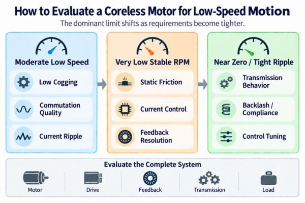
For OEM selection, the required motion profile should therefore be defined before choosing the motor, feedback method, gearbox, or drive architecture.
OEM engineers should define at least:
- Minimum stable speed and acceptable speed ripple.
- Load torque and load inertia.
- Static friction and breakaway behavior.
- Required feedback resolution.
- Driver architecture and control strategy.
- Direction-reversal and positioning requirements.
- Noise and vibration limits where relevant.
| Low-Speed Requirement | Main System Factors to Evaluate |
|---|---|
| Very Low Stable RPM | Feedback Resolution + Static Friction + Current Control |
| Low Torque Ripple | Coreless Architecture + Commutation Quality + Current Ripple |
| Quiet Operation | Current Ripple + Bearing Quality + Mechanical Mounting |
| Frequent Reversals | Rotor Inertia + Friction + Control Loop Tuning |
| Precision Positioning | Encoder Resolution + Backlash + Mechanical Compliance |
| High Load at Low RPM | Current Capacity + Thermal Limits + Transmission |
At moderate low speeds, reduced cogging may be the dominant advantage of a coreless motor5. As operating requirements move closer to near-zero motion, increasingly tight speed regulation shifts the engineering focus toward feedback resolution, friction control, current regulation, and mechanical transmission behavior6.
BODENMOTION's coreless motor platform spans brushed and brushless architectures from 10–50 mm, with configurable windings, gearboxes, shafts, and encoder options. For precision low-speed applications, these options should be evaluated together against the application's speed, load, driver, feedback, and transmission requirements.
Conclusion
Coreless motors provide a strong physical foundation for smooth low-speed motion because their ironless or slotless architecture greatly reduces the conventional tooth-slot cogging mechanism. In typical brushed coreless designs, low rotating inertia can also improve dynamic response during acceleration, positioning, and direction reversal.
Minimum stable speed, however, is ultimately a system-level result. Commutation quality, PWM current ripple, mechanical friction, transmission behavior, feedback resolution, and controller tuning can all become limiting factors as speed approaches zero. The useful selection question is therefore not simply, “Is this motor smooth?” but, “Can this motor-driver-feedback-mechanical system maintain the required speed and torque within the allowed ripple under the real application load?”
FAQ
Q1: Why are coreless motors smoother at low speed?
Their ironless or slotless architecture greatly reduces or removes the conventional tooth-slot cogging mechanism. This minimizes a major structural source of periodic torque disturbance that can cause jerky motion and speed variation at low speeds.
Q2: Do coreless motors have zero torque ripple?
No. Low cogging does not mean zero torque ripple. Other disturbances remain, including mechanical or electronic commutation effects, PWM current ripple from the driver, mechanical friction, load disturbances, and control-loop behavior.
Q3: Are brushed or brushless coreless motors smoother at low speed?
Both can achieve excellent smoothness, but their limiting factors differ. Brushed coreless motors use relatively simple mechanical commutation but can be affected by brush contact, commutator transition, and friction. Brushless coreless motors eliminate brushes but depend more heavily on electronic commutation, current regulation, and feedback quality.
Q4: Why does bearing friction matter more at very low speeds?
Near zero speed, the motor must overcome static breakaway friction before motion begins. The transition between static and dynamic friction can contribute to stick-slip behavior, particularly when combined with mechanical compliance or control-loop effects. This can become a major limit to minimum stable speed even when motor cogging is very low.
Q5: What information should OEM engineers provide for low-speed motor selection?
Provide the complete system performance requirements, including minimum stable speed, acceptable speed ripple, load torque and inertia, static friction or breakaway behavior, feedback type and resolution, intended driver and control method, and any relevant transmission characteristics. Low-speed performance is a system-level property rather than a motor-only specification.
Mabuchi Motor explains that stator teeth in slotted motors create position-dependent magnetic-reluctance variation and periodic attraction between the teeth and rotor magnets, producing cogging torque. Removing the teeth in a slotless structure greatly reduces this source of periodic torque disturbance. ↩
Celera Motion describes cogging torque as an inherent disturbance caused by the interaction between permanent magnets and stator slots. Slotless construction removes this source of uncontrolled torque disturbance, allowing torque production to depend more directly on commanded phase current and subsequent servo regulation. ↩
BODENMOTION’s comparison of brushed coreless and BLDC motors notes that brushed motors rely on mechanical brush–commutator contact, while BLDC motors use electronic commutation. Eliminating the brushes removes brush-related friction, wear, and associated performance degradation. ↩
The Virginia Tech study on direct back-EMF detection for sensorless BLDC control explains that back EMF becomes very small at low speed, making reliable detection more difficult. It also notes that conventional back-EMF sensorless schemes require the motor to reach sufficient speed before the signal can be detected reliably. ↩
The ironless/coreless motor section of the electric-motor reference identifies the absence of cogging as a distinctive advantage of ironless coreless construction, supporting reduced structural torque disturbance at low speed. ↩
Tan, Lee, and Huang’s *Precision Motion Control* shows that high-precision motion depends on high-resolution position measurement, careful treatment of friction and backlash, and proper modelling of drive and mechanical dynamics. The text also notes that effects which may be neglected under modest performance requirements must be considered explicitly as control requirements become more stringent. ↩