When selecting a brushless DC motor, engineers often focus on datasheet values like rated torque, peak torque, and maximum current. While critical, these parameters do not tell the whole story, especially for high-speed applications. At high rotational speeds, the motor's performance may become limited not by its current rating, but by the voltage available from the drive system.
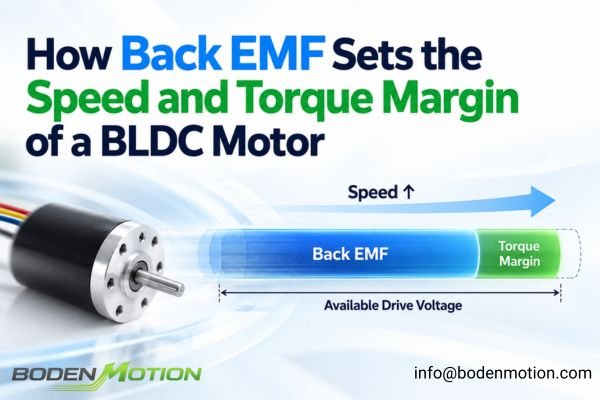
As a BLDC motor's speed increases, its internally generated back electromotive force (back EMF) rises proportionally, accounting for an increasing share of the available drive voltage. This reduces the voltage headroom available for current regulation, which in turn diminishes the motor's available torque margin. The correct engineering question is therefore not only "Can the motor reach this RPM?" but "Can the complete motor-driver system maintain the required torque at that RPM under the actual minimum bus voltage and operating conditions?"
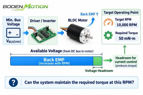
Understanding this transition requires looking at how back EMF develops with motor speed and how it interacts with winding voltage drop, inverter capability, and the required torque-producing current. These relationships determine where a BLDC system moves from having sufficient current-control margin to operating near its voltage limit.
What Is Back EMF in a BLDC Motor?
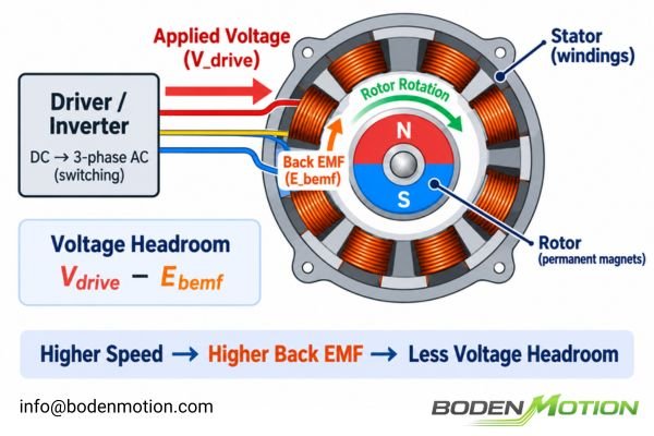
When the permanent magnets on a BLDC motor's rotor rotate relative to the stationary stator windings, the magnetic flux linkage through those windings changes continuously. According to electromagnetic induction, this changing flux generates a voltage in the windings that opposes the applied drive voltage. This induced voltage is the back electromotive force, or back EMF.
Back EMF is the electrical result of the changing magnetic flux linkage created by rotor motion. Its magnitude increases approximately in proportion to rotational speed, meaning higher speeds produce a larger opposing voltage and leave less of the available inverter voltage for regulating motor current.
The physical relationship can be expressed as:
Here, E is the back EMF, ω is the mechanical angular velocity in radians per second (rad/s), and Ke is the back-EMF constant in V/(rad/s). Motor datasheets often provide this constant in other units, such as V/krpm, so engineers must use a consistent set of units for calculations.
It's critical to note that Ke from different suppliers may be defined differently (e.g., phase-to-phase vs. phase-to-neutral, RMS vs. peak). These values must not be used in calculations without first confirming their definition.
What Does Voltage Headroom Mean in a BLDC Drive?
In a BLDC drive system, "voltage headroom" is the amount of usable voltage remaining for the controller to regulate current after accounting for the motor's back EMF and other voltage drops. This is a crucial concept for understanding high-speed performance limitations.
The voltage available from the inverter must first overcome the motor's back EMF and its resistive and inductive voltage drops. The voltage that remains is the "headroom" that the controller uses to dynamically regulate the torque-producing current. As speed increases, this headroom shrinks.
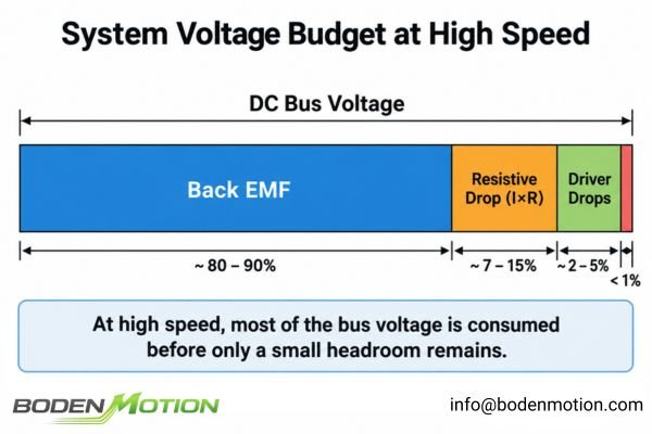
This is a conceptual voltage-budget relationship. A detailed analysis depends on the motor voltage definition, inverter topology, modulation strategy (e.g., SVPWM), and current-control method. For a more in-depth look at how the drive system influences performance, see our guide on brushless DC motor driver selection. The key takeaway is that the usable motor voltage is determined by the DC bus together with the inverter topology, modulation strategy, semiconductor voltage drops, and control limits. Engineers should therefore compare the motor's back EMF with the actual voltage available to the motor phases rather than directly with the DC supply's nameplate voltage.
Why Increasing Speed Reduces Available Torque Margin
The relationship between speed and available torque is a direct consequence of voltage headroom. Motor torque is approximately proportional to the current in its windings (T ≈ Kt × I). To produce or change torque, the controller must be able to regulate this current.
At high speeds, back EMF can approach the maximum available inverter voltage. When this happens, the controller has minimal voltage margin left to increase current in response to a load change. As the inverter approaches its maximum modulation limit, it can no longer force more current into the windings, and the available torque capability falls.
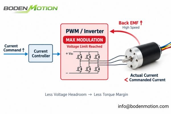
This is why a motor-driver system can fail to deliver the expected torque at high RPM, even if the commanded current is well below the driver's maximum rating. The system is no longer limited by the current capacity of its components but by the lack of sufficient voltage to overcome the motor's internal back EMF and impedance. This creates two distinct performance boundaries: a current-limited region at lower speeds and a voltage-limited region at higher speeds.
Base Speed: Current-Limited vs. Voltage-Limited Operation
The approximate operating point where the inverter begins to reach its voltage limit is known as the base speed. This is not an intrinsic motor-only specification but a system-dependent characteristic.
For a defined combination of DC bus voltage, motor winding, current limit, load, temperature, and control strategy, base speed represents the transition from a current-limited operating region, where sufficient voltage remains to regulate torque-producing current, to a voltage-limited region, where the commanded current may no longer be achievable.
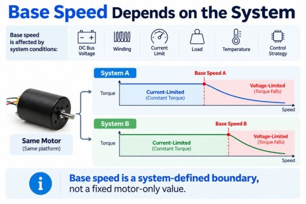
In normal operation without field weakening2, the regions are:
- Below Base Speed (Constant-Torque Region): Ample voltage headroom is available for the controller to regulate current. Torque is primarily limited by the system's current rating and thermal constraints.
- Near or Above Base Speed (Voltage-Limited Region): Voltage headroom becomes increasingly limited. The driver struggles to maintain the commanded current, and the maximum available torque declines as speed increases.
Advanced controllers can use a technique called field weakening to extend operation above the normal base-speed region. This involves trade-offs, including reduced torque capability and lower efficiency, and is not the focus of standard operation.
Why Loaded Maximum Speed Is Lower Than No-Load Speed
A motor's no-load speed on a datasheet can be misleading if taken as a guarantee of performance under load. The difference between no-load and loaded speed is explained by the interaction between back EMF, torque-producing current, and the resistive voltage drop in the windings.
At no load, the required current is very low, so the resistive voltage drop (I×R) is minimal. The motor can accelerate until its back EMF approaches the available drive voltage. Under load, producing torque requires more current, which increases the I×R voltage drop and reduces the remaining voltage headroom. As the system approaches its voltage limit, this lowers the maximum speed that can be sustained at the required torque.
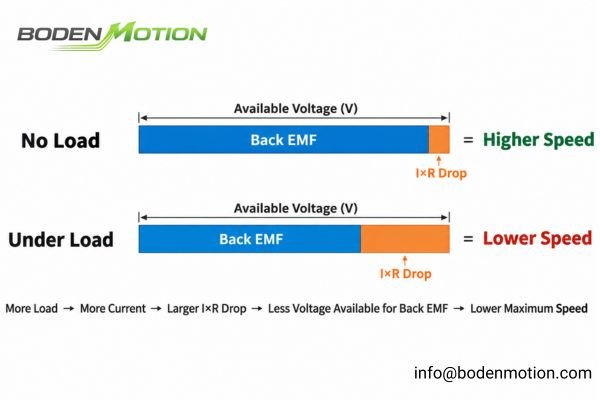
For a deeper dive into this topic, see Why Rated Speed Is Lower Than No-Load Speed in Brushless Motors. As torque demand increases, the required current and associated I×R voltage drop also increase.3 This reduces the remaining voltage headroom and, as the system approaches its voltage limit, lowers the maximum speed that can be sustained at that torque.4
| Condition | Back EMF | Current I |
Main Electrical Limitation | Result |
|---|---|---|---|---|
| No Load | High | Low | Back EMF approaches the available motor voltage. | High speed with minimal torque demand. |
| Loaded at Maximum Sustainable Speed | Lower because operating speed is lower | Higher | Back EMF and I×R drop together approach the available motor voltage. |
Lower maximum speed at the required torque. |
| Stall / Zero Speed | Approx. zero | Limited by the drive system | Controller current limit and winding resistance dominate. | Torque depends on the permitted system current and thermal limits. |
What OEM Engineers Should Provide for High-Speed Evaluation
To determine if a brushless DC motor can meet a high-speed requirement, the evaluation must consider the entire system. A simple question is not enough; a detailed operating point is required. The process involves a collaboration between the OEM and the motor supplier.
A successful high-speed evaluation requires the OEM to define the application's operating conditions and constraints. The motor supplier then uses this information to select an appropriate motor and winding and verify that sufficient voltage and thermal margin exist at the target operating point.
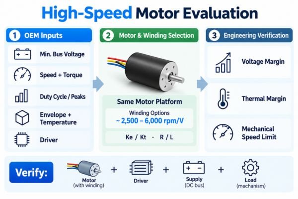
Information the OEM Should Provide:
- System Voltage: Nominal DC bus voltage and, critically, the minimum voltage under load.
- Operating Point: The target maximum speed and the required continuous torque at that speed.
- Operating Profile: Duty cycle, acceleration requirements, and peak torque demands.
- Constraints: Mechanical envelope (diameter, length), ambient temperature, and cooling conditions.
- Driver: The intended driver/controller architecture, if already determined.
Parameters the Motor Supplier Verifies:
- Motor Constants: Back-EMF constant (
Ke), torque constant (Kt), phase resistance (R), and inductance (L) for a suitable winding. - Operating Limits: Hot winding resistance, mechanical speed limits of the rotor and bearings.
- System Compatibility: Verification of the
motor + winding + driver + supply + loadcombination.
For instance, the same mechanical motor platform can have substantially different electrical speed characteristics depending on the selected winding. A BODENMOTION BDCL1525 platform (Ø15 × 25 mm) offers winding options with speed constants ranging approximately from 2,500 to 6,000 rpm/V. This illustrates why high-speed operation cannot be judged from motor dimensions alone; the winding constant, DC bus voltage, required torque, and driver must be evaluated together.
How to Check Voltage Headroom at the Target Operating Point
Engineers can perform a first-pass check to estimate if an operating point is feasible. This preliminary calculation helps screen potential motor candidates before committing to extensive testing.
This first-pass engineering check estimates the remaining voltage margin by subtracting the calculated back EMF and resistive voltage drop from the usable inverter voltage. A small or negative margin indicates the operating point is likely in the voltage-limited region and requires more detailed analysis or a system redesign.
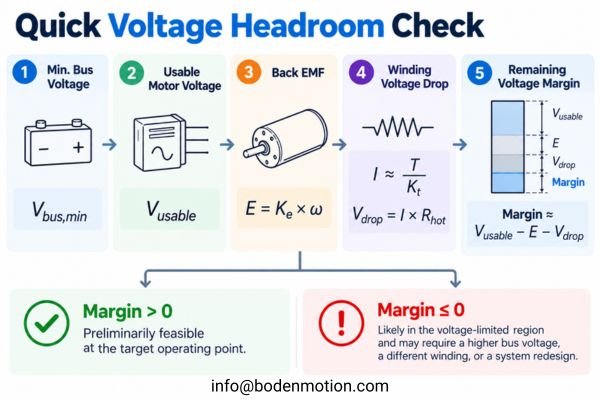
A simplified screening calculation follows these steps:
- Define Minimum Bus Voltage: Use the lowest expected DC voltage under full load.
- Determine Usable Motor Voltage: Estimate the voltage available from the inverter after accounting for its internal drops and modulation limits.
- Calculate Back EMF: Use the motor's
Keand target speed. - Calculate Voltage Drop: Determine the required current from the torque (
I ≈ T / Kt) and calculate the resistive voltage drop (V_drop = I × R_hot), using the winding resistance at the expected operating temperature. - Evaluate Remaining Margin:
Remaining Margin ≈ Usable Voltage − Back EMF − V_drop.
Final verification, especially for operating points close to the voltage limit, may also need to account for inductive and cross-coupling voltage terms that increase with electrical frequency. In FOC systems, these effects are normally evaluated using the motor's d-q voltage model rather than the simplified first-pass voltage budget above. A robust check should also evaluate motor parameters across the expected temperature and tolerance range, because copper resistance increases with winding temperature5 while magnet temperature and manufacturing variation can also affect Ke and Kt.
Conclusion
Back EMF is a fundamental property of BLDC motors that links mechanical speed to electrical voltage. While often seen as a limitation, it is an inherent part of motor operation. The critical engineering insight is understanding its effect on the system's voltage budget. The causal chain Speed ↑ → Back EMF ↑ → Voltage Headroom ↓ → High-Speed Torque Margin ↓ explains why a motor's performance can be voltage-limited at high speed, even if its current rating is not exceeded.
For OEM engineers, high-speed motor selection should therefore be based on a defined operating point rather than a no-load RPM target alone. The real question is whether the selected motor, winding, driver, and DC bus can maintain the required torque at the target speed when minimum supply voltage, duty cycle, and operating temperature are considered together. For high-speed motor evaluation or winding selection, you can share your operating requirements with our engineering team at info@bodenmotion.com.
FAQ
What is back EMF in a BLDC motor?
Back EMF is the voltage generated by the rotating motor, acting like a generator. It opposes the applied drive voltage, and its magnitude increases proportionally with speed.
Why does BLDC motor torque decrease at high speed?
In normal operation, torque decreases at high speed because the rising back EMF leaves insufficient voltage headroom for the driver to regulate the necessary torque-producing current. The system becomes voltage-limited.
What determines the base speed of a BLDC motor?
The base speed is a system-dependent operating point rather than an intrinsic motor-only specification. It depends on the DC bus voltage, selected winding and motor constants, required torque and current, operating temperature, current limit, and the driver's modulation and control strategy.
Does increasing DC bus voltage increase maximum BLDC motor speed?
Yes, a higher DC bus voltage increases the available voltage headroom, which generally allows the motor to reach a higher speed before becoming voltage-limited. This is always subject to the motor's mechanical, thermal, and insulation limits.
What is field weakening in a BLDC motor?
Field weakening is an advanced control strategy that extends a motor's speed range beyond its normal base speed. It works by using motor current to reduce the effective back EMF, but this extended speed capability comes at the cost of reduced torque and potentially lower efficiency.
Michigan State University’s *Introductory Physics for the Health and Life Sciences* explains that a rotating motor generates a back EMF that opposes the applied voltage and increases in proportion to angular velocity, supporting the relationship expressed as `E = Ke × ω`. ↩
MIT’s *Motors + Motor Control – an Overview* describes field weakening as a motor-control technique that reduces the effective permanent-magnet field to extend operation to higher rotational speeds, including operation beyond the normal base-speed region. ↩
Purdue University’s *Current Controlled Brushless DC Motor Drive* shows that electromagnetic torque in a permanent-magnet brushless DC motor is proportional to the torque-producing component of phase current, while the stator voltage equations include the winding-resistance term `R × I`. Higher torque demand therefore requires higher current and produces a larger resistive voltage drop. ↩
Purdue University’s *Current Controlled Brushless DC Motor Drive* derives a relationship between inverter source voltage and the maximum rotor speed at which regulated motor current can be maintained, supporting the conclusion that limited available voltage reduces the maximum speed sustainable at a required torque. ↩
*Electrical Resistance and Conductance* explains that the resistance of metallic conductors generally increases with temperature near normal operating temperatures, supporting the use of a higher hot resistance for copper motor windings. ↩