When designing a positioning system, engineers often start by selecting a motor and encoder combination. It is tempting to take the encoder's counts per revolution (CPR), divide 360° by that number, and assume the result is the system's achievable positioning accuracy. This calculation, however, only describes the theoretical measurement granularity of one component.
Encoder counts describe the smallest increment of motion the system can measure, not the guaranteed positioning accuracy of the final mechanism. Unlike a stepper motor, a coreless DC motor does not have an inherent mechanical step resolution. In a closed-loop system, its effective positioning capability is determined by the entire architecture: the feedback device, control loop, and—critically—mechanical transmission components like gearboxes, couplings, and shafts, which introduce errors that degrade final performance.
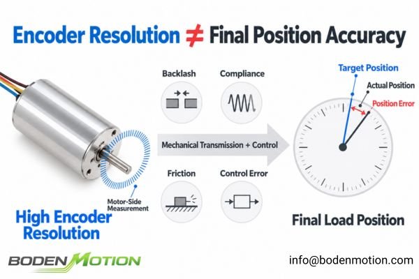
To evaluate positioning performance realistically, engineers need to follow the feedback signal from encoder counts at the motor shaft through the gearbox, mechanical transmission, and control loop to the final load. This also requires separating theoretical resolution from repeatability and absolute accuracy, because each describes a different layer of system performance.
What Does Encoder Resolution Actually Mean?
Encoder resolution specifies how finely the angular movement of a shaft can be measured. It is the fundamental building block of a position feedback system. However, terms like PPR (pulses per revolution), CPR (counts per revolution), and lines per revolution are not always used consistently by suppliers, so confirming the definition is the first critical step.
Encoder resolution tells you how finely the motor's position can be observed by the controller—not how precisely the mechanism can physically stop. The final count resolution depends on both the encoder's physical characteristics and how the controller decodes its signals. For a typical incremental quadrature encoder, x4 decoding is common but must be confirmed.
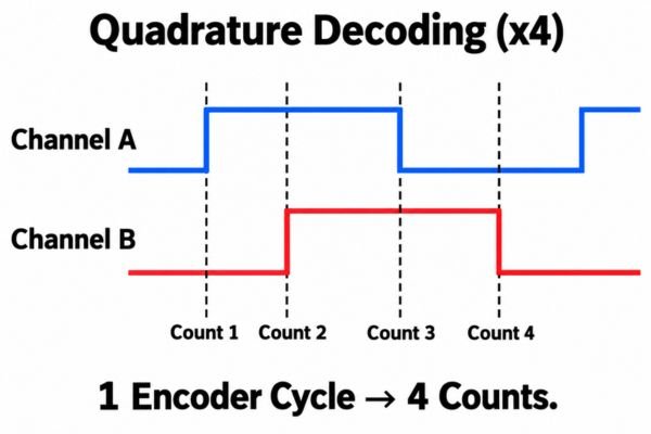
For example, if a supplier's 500 PPR specification refers to 500 A-channel cycles per revolution, and the controller uses x4 quadrature decoding to count the rising and falling edges of both the A and B signals1, the result is:
- Effective CPR: 500 cycles/rev × 4 counts/cycle = 2,000 counts/rev
- Theoretical Angular Increment: 360° / 2,000 counts = 0.18° per count
This 0.18° value is the system's measurement resolution at the motor shaft. It is the smallest change the controller can detect, but it does not yet tell us about the system's positioning repeatability, absolute accuracy, or the smallest physical move the output shaft can make. A complete understanding of DC coreless motor position control requires looking at the entire system.
How Gear Ratio Changes Theoretical Motor and Output Resolution
In many positioning systems, a gearbox is used to reduce speed and increase torque. A secondary effect is that a reduction gearbox multiplies the theoretical resolution at the output shaft, which can seem like a significant advantage for achieving precision.
A gear ratio mathematically multiplies the motor-side encoder resolution, resulting in a much finer theoretical angular resolution at the output shaft. However, the gearbox simultaneously introduces mechanical error sources like backlash and transmission error, which can degrade the actual bidirectional positioning accuracy, often by an amount far greater than the theoretical resolution.
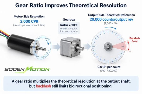
Using our previous example with a 10:1 reduction gearbox:
- Motor-Side Resolution: 2,000 CPR
- Output-Side Resolution: 2,000 counts/motor-rev × 10 motor-revs/output-rev = 20,000 counts/output-rev
- Theoretical Output Increment: 360° / 20,000 counts = 0.018° per count
On paper, the system's resolution has improved tenfold. However, the physical gears have clearances (backlash2) and elastic deflection3 that prevent this theoretical precision from being fully realized, especially when the load must reverse direction.
Resolution, Repeatability, and Accuracy Are Three Different Specifications
A primary source of error in positioning system design is confusing the concepts of resolution, repeatability, and accuracy. They are distinct, hierarchical parameters, and a system can easily have high resolution but poor accuracy.
Resolution is the smallest measurable move, repeatability is the ability to consistently return to a target position, and absolute accuracy is the deviation from a true commanded position. The relative importance of repeatability and accuracy depends on the application, and both can be much coarser than the system's theoretical resolution.
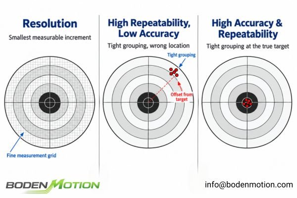
A critical distinction exists between unidirectional and bidirectional repeatability. When a target is always approached from the same direction, the effect of backlash on repeatability can be greatly reduced because the gear train remains loaded against the same tooth flanks. However, if the system must approach the target from opposite directions, backlash becomes a major component of the positioning error. Therefore, bidirectional repeatability is a more demanding specification for applications with reversing motion.
| Parameter | What It Means | Main Limiting Factors |
|---|---|---|
| Resolution | Smallest measurable position increment. | Encoder counts, interpolation. |
| Unidirectional Repeatability | Ability to return to the same position from the same direction. | Friction, control loop stability. |
| Bidirectional Repeatability | Ability to return to the same position from opposite directions. | Backlash, hysteresis, system compliance. |
| Absolute Accuracy | Difference between the commanded and true physical position. | System calibration, gear transmission error, encoder accuracy. |
How Backlash, Shaft Compliance, and Friction Reduce Real Positioning Performance
The gap between theoretical resolution and real-world performance is due to physical imperfections in the mechanical transmission path. A motor-mounted encoder directly measures motor shaft motion but cannot see what happens downstream.
Mechanical errors like gear backlash, torsional compliance, and friction introduce non-linear behaviors that are invisible to a motor-mounted encoder. These factors create dead zones, hysteresis, and position-dependent errors that are often the dominant limitations on system repeatability and accuracy.
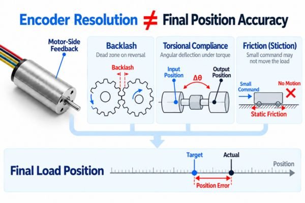
Key error sources include:
- Gear Backlash4: The clearance between gear teeth creates a dead zone when reversing direction. The motor shaft can turn several encoder counts before the output load begins to move, creating a significant bidirectional positioning error.
- Shaft and Coupling Compliance: Mechanical components deform elastically under torque. As a result, the load position can differ from the motor-side encoder position by a torque-dependent angular deflection, even when the motor shaft has reached its commanded count.
- Friction: Static friction (stiction) can prevent the mechanism from responding to very small, single-count position commands. The controller may command a move, but the motor torque might be insufficient to overcome the initial friction.
The location of the encoder is critical. A motor-side encoder is blind to errors that occur after it in the transmission path. For very high-precision systems, designers may consider adding a second encoder at the final load (load-side feedback) to directly measure these downstream errors and enable the control architecture to account for them.
Why More Encoder Counts Can Stop Helping
There is a point of diminishing returns where increasing encoder resolution adds cost without providing a meaningful improvement in positioning performance. This occurs when other system errors are significantly larger than the encoder's measurement increment.
Encoder resolution should be selected so that it is not the dominant error source in the system budget. At the same motor speed, increasing CPR increases the pulse frequency and count rate. More counts are useful only when the complete feedback and control system—including the encoder interface, wiring, controller hardware, and control architecture—can use them reliably.
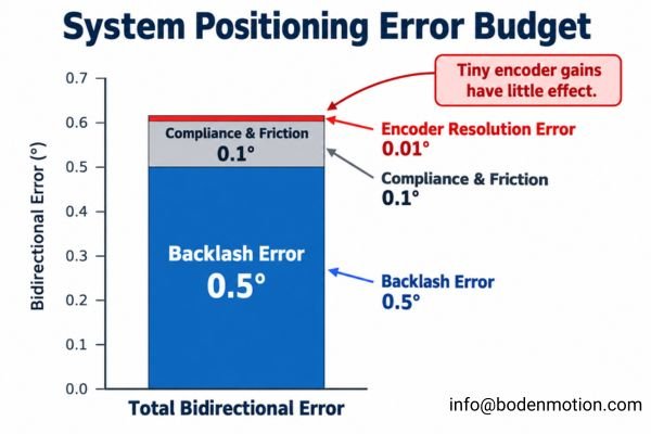
Increasing encoder counts stops being effective when limited by:
- Mechanical Errors: If the system has 0.2° of gear backlash, improving encoder resolution from 0.01° to 0.001° will not improve the system's bidirectional repeatability. The mechanical error is the dominant factor.
- Encoder Interface Bandwidth: A high-CPR encoder can generate a very high pulse or count rate at maximum motor speed. The encoder input hardware must be able to capture this signal without exceeding its maximum input frequency or losing counts.
- Control-Loop Bandwidth: Higher measurement granularity is only useful when the position-control architecture can make effective use of that information at the required speed, load, and settling time.
- Signal Integrity: A higher count rate requires sufficient bandwidth from the encoder interface, wiring, and controller input stage. Electrical noise or poor signal transmission can cause missed or false counts if the interface is not designed appropriately.
What OEM Engineers Should Provide for Positioning-System Evaluation
To design a successful positioning system, the conversation with a motor supplier must move beyond a simple request for encoder CPR. A proper evaluation requires defining the performance requirements of the final load under real-world operating conditions.
Instead of asking for a specific encoder count, OEM engineers should define the required output performance of their system. This includes the target repeatability, absolute accuracy, and motion profile, as these system-level requirements dictate the necessary motor, gearbox, and encoder combination.
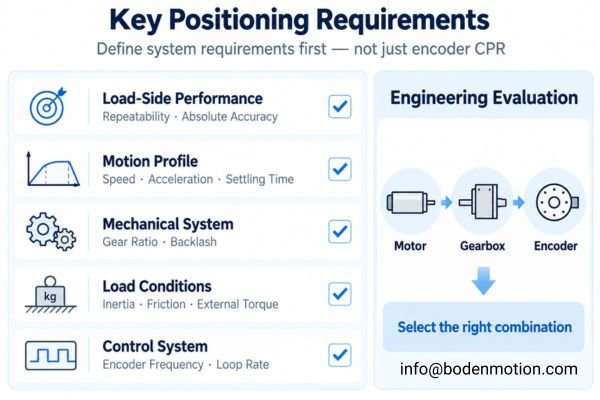
A productive inquiry defines the real system requirement by providing:
- Required Load-Side Performance: Target repeatability (unidirectional and/or bidirectional) and absolute accuracy.
- Motion Profile: Maximum speed, acceleration, and required settling time.
- Mechanical System: Gear ratio and expected gearbox backlash.
- Load: Load inertia, friction, and any external torques.
- Control System: Controller maximum encoder input frequency and position-loop sampling rate.
For example, the BDCB2225 22mm coreless gear motor can be configured with an optional planetary gearbox and photoelectric or magnetoelectric encoder feedback. In this type of motor–gearbox–encoder architecture, the appropriate feedback configuration cannot be determined from CPR alone. Gear ratio, required output-side repeatability, motor speed, controller interface, and available installation space all need to be evaluated together.
Moving from "Can you provide a 1000 PPR encoder?" to "We need to achieve ±0.1° bidirectional repeatability at the output of a 20:1 gearbox" allows for a much more effective engineering solution.
How to Estimate Positioning Capability From Encoder to Final Load
To understand the relationship between encoder counts and final performance, it's useful to build a system error budget. This provides a realistic, layered view of the final positioning capability, moving beyond a single theoretical number.
Theoretical resolution can be calculated, but actual positioning capability must ultimately be validated by measurement. The estimation process requires building a system error budget that distinguishes between measurement resolution and the effects of direction-dependent, load-dependent, and dynamic errors.
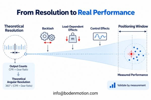
Building an error budget is more complex than adding static tolerances. It involves evaluating how different error sources contribute under specific conditions.
- Establish Theoretical Resolution: Start with the effective CPR at the motor shaft and apply the gear ratio to find the theoretical resolution at the load.
- Budget for Mechanical Errors: Quantify the impact of key mechanical errors. Backlash is a direction-dependent error, while compliance is a load-dependent error. These are not static values.
- Account for Control and Settling Effects: The control loop's ability to settle at a target position without excessive overshoot, hunting, or residual error contributes to the final positioning window.5
| Layer | Contribution to Error Budget | Nature of Error |
|---|---|---|
| Encoder Quantization | The fundamental measurement granularity. | Discretization |
| Gear Backlash | Creates a "dead zone" on direction reversal. | Direction-Dependent |
| System Compliance | Causes torque-dependent deflection under load. | Load-Dependent |
| Friction | Creates a minimum motion threshold (stiction). | Non-Linear, Threshold |
| Control Loop | Tracking error and settling stability. | Dynamic, Tuning-Dependent |
Conclusion
High encoder resolution is a valuable tool in a precision positioning system, but it is only the first step in a chain that determines final performance. The path from encoder counts to the final load's positioning performance includes mechanical and control-system limitations that may be far larger than the theoretical measurement increment. The core engineering logic follows a clear cascade: Encoder CPR → Motor-Shaft Measurement Resolution → Gear Ratio → Theoretical Load-Side Resolution → Mechanical Error Budget → Control Limitations → Actual Positioning Performance. High CPR is useful only when the encoder's measurement granularity is sufficiently finer than the dominant mechanical and control errors.
When selecting a motion solution, OEM engineers should focus on the final system-level requirements rather than maximizing a single encoder specification. The required load-side repeatability and absolute accuracy should be defined together with the gear ratio, motion direction, maximum speed, load conditions, and control requirements. This makes it possible to evaluate a balanced combination of coreless motors, gearboxes, and feedback components without over-specifying one part of the system. For a new positioning application, these operating conditions provide a much more useful starting point for engineering evaluation than CPR alone. To discuss motor, gearbox, and encoder requirements for a specific application, contact our engineering team at info@bodenmotion.com.
FAQ
Q1: What is the difference between PPR and CPR?
Definitions vary by manufacturer. PPR (pulses per revolution) may refer to the physical lines or quadrature cycles on the encoder disk. CPR (counts per revolution) often refers to the final decoded counts. For example, a 500-cycle encoder can produce 2,000 CPR if the controller uses x4 quadrature decoding. Always confirm the supplier's exact definition.
Q2: Does a higher encoder resolution improve motor positioning accuracy?
It improves the measurement granularity, but the system's final positioning accuracy and repeatability may still be limited by larger mechanical errors like gear backlash, shaft compliance, friction, and the performance of the control loop.
Q3: How does a gearbox affect encoder resolution?
A reduction gearbox multiplies the number of motor-side encoder counts for each output revolution, which improves the theoretical resolution at the output. However, the gearbox also introduces mechanical errors like backlash that can degrade the actual positioning performance, especially bidirectional repeatability.
Q4: What is the difference between repeatability and absolute accuracy?
Repeatability is the ability of a system to consistently return to the same position. It can be defined for unidirectional or bidirectional motion. Absolute accuracy is the difference between the system's actual position and the true, ideal commanded position. A system can be highly repeatable but have poor absolute accuracy before calibration.
Q5: What information should OEM engineers provide for encoder selection?
Instead of just an encoder count, provide the system-level performance requirements: target output repeatability (unidirectional and bidirectional), absolute accuracy, gear ratio, expected backlash, load inertia, maximum motor speed, and the controller's maximum encoder input frequency and position-loop sampling rate.
“Incremental Encoder” explains that one full quadrature cycle contains four signal transitions—rising and falling edges on both the A and B channels—so x4 decoding produces four counts per encoder cycle. ↩
Florida State University’s “Method of Mitigating Backlash of Mechanical Gear Systems Using a Damper Motor” describes backlash as a practical limitation in mechanical gear systems and presents a method for reducing its effect at the gearbox output. ↩
Rutgers University’s “A Study of Large Deflection of Beams and Plates” describes elastic deformation under mechanical loading and shows that structural deflection depends on stiffness, supporting elastic deflection as a source of mechanical displacement error. ↩
The NIST paper “Degradation Modeling of a Robot Arm to Support Prognostics and Health Management” shows that gear backlash creates free movement before the driving and driven gears fully engage. During a direction reversal, this produces a deadband in which the input moves while the output remains unchanged until the gears re-engage. ↩
“PID Controller” describes settling time, overshoot, oscillation around the setpoint, and steady-state error as important characteristics of closed-loop response, supporting their contribution to the final positioning behavior of a controlled system. ↩