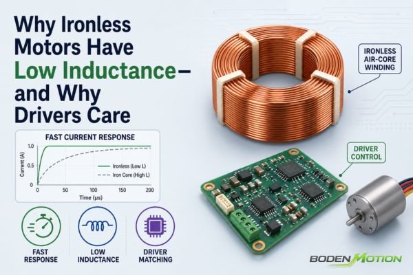
You chose an ironless DC motor for its fast response, but now your driver is overheating or the motor is noisy. The problem often isn't a faulty component but an electrical mismatch, where the driver's control capabilities are not well-matched to the motor's rapid electrical dynamics.
Ironless motors have low inductance because their windings lack an iron core. This feature enables a fast electrical response but also changes the requirements placed on the driver, particularly for PWM strategy and current regulation, to ensure stable and efficient operation.
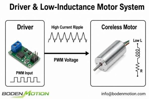
This low inductance creates a direct trade-off for system design. It is the key to the motor's dynamic performance, yet it modifies the electrical relationship between the motor and the driver. Understanding this characteristic is critical for avoiding common integration issues like excess heat, poor performance, and control instability1.
Why Ironless Motors Have Lower Inductance
The quick response of an ironless motor stems from its unique construction, which also defines its electrical signature. The defining feature is what's missing: the traditional iron core within the winding structure.
Ironless motors have lower inductance because their windings are not built on a ferromagnetic iron core. This design lowers the magnetic permeability of the flux path, reducing the magnetic flux linkage per unit of current and thus storing less magnetic energy.
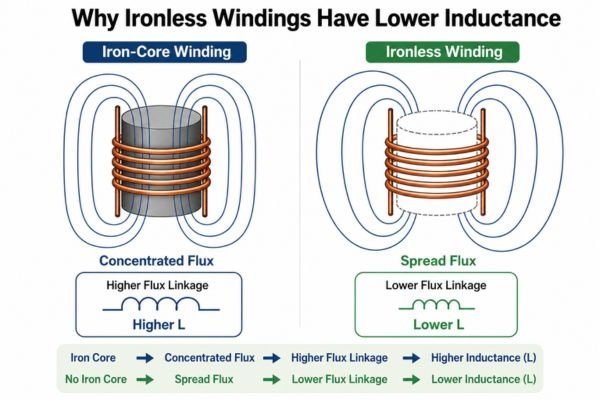
In conventional iron-core motor designs, the windings are supported by or wound around laminated ferromagnetic teeth or an iron armature, depending on the motor architecture. This iron core has high magnetic permeability, concentrating magnetic flux and generally resulting in a higher winding inductance.
Ironless motor designs remove this iron from the winding structure.
- Coreless Brushed DC Motors typically use a self-supporting "cup" or "bell" shaped rotor winding that rotates around a central stator magnet.
- Slotless BLDC Motors use a stator winding that is wound and secured in the stator housing without being placed in iron slots.
Across the BODENMOTION ironless motor platform, different brushed and brushless configurations may use various constructions depending on motor size and performance targets, including self-supporting, skewed, or saddle-shaped ironless winding designs. Although the specific inductance L still depends on winding geometry, size, and number of turns, removing the high-permeability iron from the winding's immediate magnetic path is the primary reason for their characteristically low inductance2.
| Feature | Iron-Core Motor Design | Ironless Motor Design |
|---|---|---|
| Winding Support | Ferromagnetic Core or Teeth | Self-Supporting or Slotless |
Magnetic Permeability (μ) |
High | Low (closer to air) |
| Magnetic Energy Storage | High | Low |
| Resulting Inductance (L) | Generally Higher | Generally Lower |
System-Level Observation:
An "ironless" motor is not a single category with one inductance value. When evaluating motors, engineers should always reference the specific inductance
Land resistanceRfrom the datasheet for the chosen winding configuration, as these values define the electrical behavior the driver must control.
How Motor Inductance Affects Electrical Response
The lower inductance described above matters because it changes how quickly winding current can respond to an applied voltage. This electrical speed is the foundation of the motor's mechanical performance.
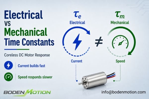
Motor inductance directly governs the electrical time constant (τe = L/R), which describes how quickly current changes in the windings. A lower inductance reduces this time constant, allowing winding current—and therefore torque—to respond rapidly to changes in applied voltage.
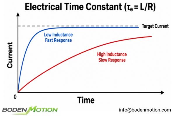
In any DC motor, torque is proportional to current (T ≈ Kt * I)3. To change torque quickly, you must change current quickly. A low L/R electrical time constant enables this fast current response.
This electrical behavior should not be confused with the motor's mechanical response.
- Electrical Time Constant (L/R): Describes how quickly the current responds.
- Mechanical Time Constant: Describes how quickly the motor's speed responds to a torque command, factoring in rotor inertia and electromechanical characteristics.
For context, selected BODENMOTION ironless motor configurations can achieve a mechanical time constant as low as approximately 1.9 ms, depending on motor size, winding, and configuration. This illustrates how quickly some configurations can respond mechanically, while remaining distinct from the L/R electrical time constant discussed above.
Why Low Inductance Creates Current Ripple Challenges
That faster current response is beneficial for dynamic motion, but it introduces the main electrical trade-off of low-inductance motors: larger current ripple when operated with a PWM driver.
Motor drivers commonly use Pulse Width Modulation (PWM) to apply a switched voltage to the windings. During each PWM cycle, current rises and falls according to the applied voltage, back-EMF, resistance, and inductance (di/dt ≈ (V - Vbemf) / L). With low inductance, this rate of change is much higher, increasing the peak-to-peak current ripple.
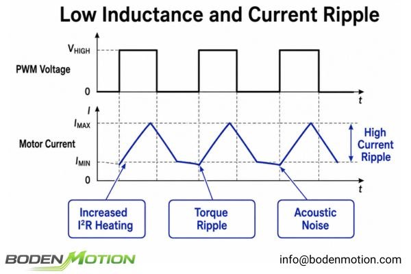
In current-regulated drives, a control loop additionally adjusts the PWM duty cycle to track a commanded current, but the physical ripple behavior within each switching cycle still exists. This ripple has several negative effects:
- Increased Motor Heating: Current ripple increases the total RMS current. Since heating is proportional to I²R, this additional ripple generates heat without producing useful average torque.4
- Torque Ripple: Fluctuations in current translate directly into fluctuations in torque, which can affect application smoothness.5
- Acoustic Noise: High-frequency torque ripple can cause mechanical vibrations that result in audible noise.
In OEM applications, average current can remain within the nominal motor rating while high ripple raises RMS current enough to cause unexpected overheating. The driver and its PWM strategy must be able to limit this ripple to an acceptable level.
Why PWM Frequency Matters for Ironless Motor Drivers
Once current ripple becomes a limiting factor, the PWM frequency is one of the first design variables engineers can adjust. The choice, however, involves a critical system-level trade-off.
Increasing the PWM frequency reduces the time available for current to rise and fall during each switching cycle, effectively shrinking the current ripple in low-inductance motors but at the cost of higher switching losses in the driver.
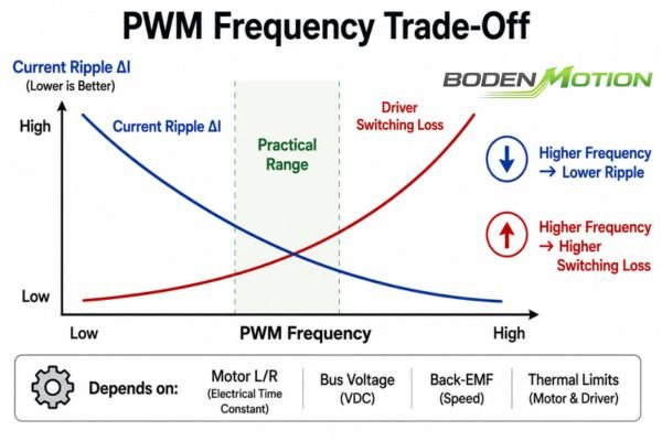
By switching faster—for example, increasing frequency from 20 kHz to 50 kHz—you give the current less time to build up or decay before the next switch reverses the process. This can reduce motor heating and minimize torque ripple.6
However, this creates a new problem for the driver. Every time a power MOSFET in the driver switches, it generates a small amount of heat (switching loss).7
- Higher PWM Frequency Trade-Offs:
- Pro: Reduces motor current ripple, motor heating, and torque ripple.
- Con: Increases driver switching losses and driver heating.
- Con: Can create more high-frequency EMI challenges.
The optimal PWM frequency is not a fixed number; it depends on the motor's inductance and resistance, the system bus voltage, motor speed (Back-EMF), and the thermal limits of both the motor and the driver. The goal is to find a balance that minimizes total system losses and keeps both components within their safe operating temperatures.
How Low Inductance Affects Driver Selection
PWM frequency alone does not determine whether a low-inductance motor and driver will operate well together. The driver's internal control architecture is just as important as its voltage and current ratings.
Drivers intended for precise current regulation of very low-inductance motors typically require sufficient current-loop bandwidth and switching capability to accurately regulate the rapidly changing current.
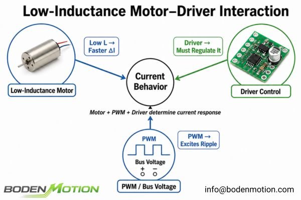
If a driver's current control loop is too slow relative to the motor's electrical time constant, the result may be excessive current ripple, poor current regulation, or control oscillation. Key driver capabilities to verify include:
- Current-Loop Bandwidth8: The control loop must be fast enough to correct errors before the current deviates too far.
- Minimum Supported Inductance9: Some drivers are not designed for very low-inductance loads and may specify a minimum required motor inductance for stable operation.
- External Inductance: For very low-inductance slotless BLDC systems, adding external inductors in series can be a mitigation option. However, this adds cost, size, and losses, and it slows the system's electrical response. For brushed coreless motors, external inductance must also be evaluated for its potential impact on commutation and brush life, so its suitability is not guaranteed.
What OEM Buyers Should Confirm When Matching Drivers With Ironless Motors
To prevent costly integration delays, motor and driver selection should be treated as one system-level task rather than two independent component decisions.
OEM buyers must provide a full electrical profile—not just mechanical needs—to ensure a stable and efficient motor-driver match. This includes motor parameters, bus voltage, operating speed, and driver capabilities.
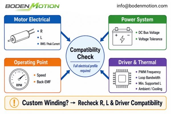
Here is the critical information needed to properly evaluate compatibility:
- Motor Winding Parameters: Winding resistance (R) and inductance (L) are essential.
- Current Requirements: Continuous (RMS) and peak current needs.
- System Voltage: Nominal DC bus voltage and its tolerance (e.g., 24V ±10%).
- Operating Speed / Back-EMF: The motor's speed affects the available voltage for current control.
- PWM Frequency Capability: The target or available PWM frequency from the driver.
- Driver Control Loop Details: Bandwidth and minimum supported load inductance, if specified.
- Thermal Environment: Ambient temperature and cooling options for both motor and driver.
If you are considering an application-specific winding to optimize for a certain voltage or speed, remember that this will change R and L. Driver compatibility must be rechecked for the final winding configuration.
Ironless Motor Driver Matching Guide
Once the motor, driver, and operating parameters are defined, the final matching logic becomes much easier to summarize. A successful match aligns the driver's capabilities with the specific electrical demands of the ironless motor's fast current dynamics.
The core engineering task is to select a driver that can manage the motor's low inductance and fast response without introducing excessive ripple or control issues, all while operating within system thermal constraints.
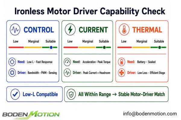
This table breaks down that relationship from a practical engineering perspective.
| If Your Ironless Motor Has/Needs... | Then Your Driver Must Provide... | Why It Matters |
|---|---|---|
| Low Inductance | Adequate bandwidth for current regulation & low-inductance compatibility | Where closed-loop current control is used, insufficient bandwidth can lead to poor regulation or oscillation. |
| Fast Torque Response | Sufficient PWM frequency for the motor L and bus V | To minimize the current ripple that causes torque ripple and motor heating10. |
| High Acceleration | Sufficient Peak Current & Headroom | To supply the necessary burst of current without tripping over-current protection. |
| Precision Motion | Accurate & Fast Current Sensing | The quality of the control loop depends on the quality of its feedback information. |
| Low Acoustic Noise | Switching strategy above the audible range, where appropriate | Can reduce PWM-related audible excitation; mechanical and electromagnetic noise must still be evaluated. |
| Compact/Sealed Enclosure | High Efficiency / Low Switching Loss | To minimize the heat the driver itself generates, preventing thermal throttling. |
| Battery Power | Efficient Power Stage & Control Strategy | To balance dynamic response with maximizing operating life from a limited power source. |
Conclusion
The low inductance of ironless motors enables fast current response and dynamic motion, but it also increases the demands placed on the driver's PWM control, current regulation, and thermal management.
Therefore, the motor and driver should be evaluated as one integrated system. If you are evaluating an ironless motor for an OEM application, sharing the motor winding parameters, bus voltage, operating speed, current requirements, and intended driver makes it much easier to identify potential compatibility risks before prototype testing. For technical support, contact our team at info@bodenmotion.com.
FAQ
Q1: Why do ironless motors have low inductance?
Ironless motors have windings that are not built on a traditional iron core. This design lowers the magnetic permeability of the flux path, reducing the amount of magnetic energy stored and resulting in generally lower inductance.
Q2: Is low inductance always better for a motor?
Not necessarily. While low inductance reduces the electrical time constant and allows winding current to respond faster, it also creates challenges like higher current ripple, which places greater demands on the driver's PWM strategy and current regulation capabilities.
Q3: Why do low-inductance motors place greater demands on drivers?
Because current changes much more rapidly, a driver intended for precise control needs a higher-bandwidth current loop, faster current sensing, and often a higher PWM frequency to maintain stable and efficient operation without excessive ripple or instability.
Q4: How does PWM frequency affect current ripple?
A higher PWM frequency shortens the switching interval, giving the current less time to rise or fall. This reduces the peak-to-peak current ripple in the motor, which in turn can lower extra heating and torque fluctuations.
Q5: What parameters should OEM engineers check when matching the motor and driver?
Key parameters include the motor's winding resistance (R) and inductance (L), the system's DC bus voltage, peak and continuous current requirements, operating speed range, and the driver's current loop bandwidth, PWM frequency capability, and minimum supported load inductance.
"Inductance - ADVANCED Motion Controls", https://www.a-m-c.com/experience/technologies/motor-characteristics/inductance/. A university engineering textbook on electric motor integration notes that proper understanding of motor inductance is essential to prevent issues such as overheating, performance degradation, and instability in control systems. Evidence role: expert_consensus; source type: education. Supports: Understanding this characteristic is critical for avoiding common integration issues like excess heat, poor performance, and control instability.. Scope note: The textbook provides general guidance and may not address all specific integration scenarios. ↩
"Ironless, Axial Flux, Electric BLDC Motor for Aircraft Electric ...", https://scholarworks.uark.edu/cgi/viewcontent.cgi?article=1081&context=eleguht. A review of ironless motor designs confirms that the absence of high-permeability iron in the winding's magnetic path significantly reduces inductance compared to iron-core motors, as discussed in technical literature on motor winding structures. Evidence role: mechanism; source type: education. Supports: removing the high-permeability iron from the winding's immediate magnetic path is the primary reason for their characteristically low inductance.. Scope note: The reduction in inductance is generally observed, but specific values depend on winding geometry and motor design. ↩
"The DC Motor", https://www.ece.rice.edu/~jdw/435/book/ch8. Standard DC motor theory establishes that torque is proportional to armature current, with the proportionality constant being the motor's torque constant (Kt). Evidence role: definition; source type: education. Supports: torque is proportional to current (`T ≈ Kt * I`). Scope note: This relationship holds for ideal DC motors and may be affected by non-linearities or saturation in practical cases. ↩
"PWM, PWM scheme (2 level, 3 level), Current ripple, Motor heating", https://support.maxongroup.com/hc/en-us/articles/360012627240-PWM-PWM-scheme-2-level-3-level-Current-ripple-Motor-heating. A technical review by the IEEE confirms that current ripple in PWM-driven motors increases the RMS current, leading to additional resistive heating that does not contribute to average torque output. Evidence role: mechanism; source type: paper. Supports: Current ripple increases the total RMS current. Since heating is proportional to I²R, this additional ripple generates heat without producing useful average torque.. Scope note: The review focuses on general motor types and PWM strategies; specific heating effects may vary with motor design and application. ↩
"What is torque ripple and how does it affect linear motion applications?", https://www.linearmotiontips.com/what-is-torque-ripple-how-does-it-affect-linear-motion-applications/. A university engineering textbook explains that in electric motors, torque is proportional to current, so current ripple causes corresponding torque ripple, impacting smoothness. Evidence role: mechanism; source type: education. Supports: Fluctuations in current translate directly into fluctuations in torque, which can affect application smoothness.. Scope note: The explanation is based on idealized motor models; real-world effects may be influenced by additional factors such as mechanical damping. ↩
"Understanding the Effect of PWM When Controlling a Brushless DC ...", https://www.portescap.com/en/newsroom/whitepapers/2021/10/understanding-the-effect-of-pwm-when-controlling-a-brushless-dc-motor. Research on PWM frequency in motor control demonstrates that increasing switching frequency reduces current ripple and torque ripple, which can lead to lower motor heating. This is supported by studies on inverter-fed motor drives, though the exact reduction depends on motor parameters and operating conditions. Evidence role: mechanism; source type: paper. Supports: Increasing PWM frequency reduces motor heating and torque ripple by limiting current ripple.. Scope note: The degree of reduction in heating and torque ripple varies with motor type and system configuration. ↩
"Behavior, Switching Losses, and Efficiency Enhancement ...", https://digitalcommons.du.edu/cgi/viewcontent.cgi?article=1051&context=electrical_engineering_faculty. Technical literature on power electronics confirms that MOSFETs incur switching losses during each transition, contributing to heat generation in the driver circuitry. The magnitude of these losses depends on switching frequency and device characteristics. Evidence role: mechanism; source type: education. Supports: MOSFETs generate heat due to switching losses during each transition.. Scope note: Switching loss magnitude varies with device and circuit design. ↩
"An Advanced Closed-Loop Control to Improve the ...", https://fab.cba.mit.edu/classes/865.18/motion/steppers/ieee-advanced-step-control-2017.pdf. Scholarly sources on motor control systems emphasize that adequate current-loop bandwidth is necessary to ensure timely correction of current errors, supporting the claim that insufficient bandwidth can lead to poor regulation and instability. This is a general principle in control engineering, though specific bandwidth requirements depend on motor and application parameters. Evidence role: expert_consensus; source type: education. Supports: The control loop must be fast enough to correct errors before the current deviates too far.. Scope note: Exact bandwidth requirements may vary depending on motor type and application. ↩
"Low Inductance Motors - Achieving Optimal Motion System Performance", https://novanta.com/robotics-automation/technical-paper/achieving-optimal-motion-system-performance-with-low-inductance-motors/. Technical documentation and engineering literature indicate that certain motor drivers specify a minimum inductance requirement to ensure stable operation, particularly with low-inductance motors. This is a recognized constraint in driver design, though the minimum value is manufacturer- and application-specific. Evidence role: general_support; source type: education. Supports: Some drivers are not designed for very low-inductance loads and may specify a minimum required motor inductance for stable operation.. Scope note: Minimum inductance values are not universal and depend on driver design. ↩
"Understanding the Effect of PWM When Controlling a Brushless DC ...", https://www.portescap.com/en/newsroom/whitepapers/2021/10/understanding-the-effect-of-pwm-when-controlling-a-brushless-dc-motor. Technical sources indicate that higher PWM frequencies reduce current ripple, which in turn minimizes torque ripple and associated motor heating in electric motors. This relationship is well-established in motor control literature, though the degree of impact depends on motor type and application. Evidence role: mechanism; source type: education. Supports: To minimize the current ripple that causes torque ripple and motor heating.. Scope note: The effect is most pronounced in motors with low inductance and may vary with different motor architectures. ↩