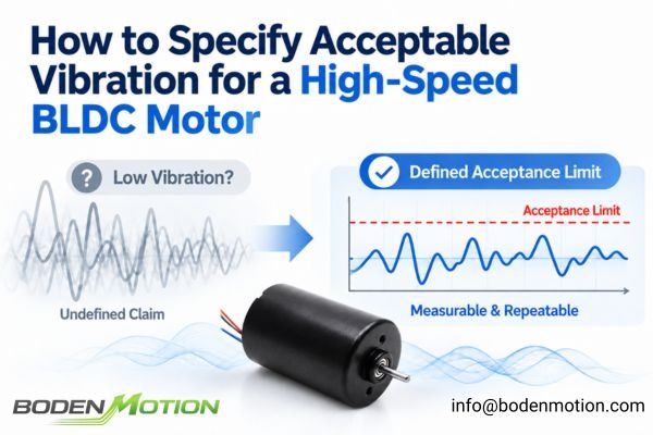
"Low vibration" is a common marketing phrase, but it is not an engineering specification. For any high-speed BLDC motor, excessive vibration can generate acoustic noise, increase bearing load, and degrade the performance of the equipment it's installed in.
A supplier’s claim of “low vibration” is insufficient for OEM qualification or quality control. A meaningful vibration specification must precisely define what is measured, how it is measured, under which conditions, and what numerical limit determines acceptance.
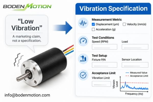
The critical question is not simply whether a motor vibrates, but whether its vibration remains within a defined and repeatable acceptance range under its intended operating conditions. Establishing this specification is the key to ensuring consistent quality from prototype to mass production and creating a clear, objective standard for both the supplier and the OEM.
What Does Motor Vibration Measurement Actually Tell You?
Before setting a limit, it's essential to understand what physical quantity is being measured. Vibration, noise, and mechanical runout are related but are not interchangeable metrics.
A vibration limit is only meaningful when the measured quantity (e.g., velocity, acceleration), amplitude convention (e.g., RMS, peak), and measurement location are all clearly specified.

Engineers typically measure one of the following:
- Vibration Displacement: The physical amplitude of oscillatory motion, often measured in micrometers (μm). It is useful for evaluating low-frequency vibration and relative movement. This should not be confused with shaft runout, which describes the measured radial or axial variation of a rotating surface relative to a reference axis or datum.
- Vibration Velocity: The rate of change of displacement, commonly measured in millimeters per second (mm/s). It is often used as a general indicator of vibration severity across a defined frequency range.
- Vibration Acceleration: The rate of change of velocity, measured in meters per second squared (m/s²) or g (multiples of gravitational acceleration). It is particularly sensitive to high-frequency events such as bearing impacts and electromagnetic excitation.
- Acoustic Noise: The sound pressure level generated by the motor and its surrounding environment, measured in decibels (dB(A)). This is a system-level acoustic measurement, not a direct measurement of mechanical vibration.
A specification must also distinguish between vibration measured on the motor housing, shaft runout measured on the shaft or another rotating surface, and vibration measured on the complete machine assembly.
Which Vibration Metric Should OEM Engineers Specify?
The choice of metric depends entirely on the application's sensitivity and the frequency range of interest. There is no single "best" metric for all high-speed BLDC motors.
For high-speed motors, acceleration is often used to capture high-frequency components, while velocity can provide a good overall assessment of severity. The correct choice depends on what the OEM is trying to protect: structural integrity, acoustic performance, or positioning accuracy.

Here is a comparison to guide the decision:
| Measurement Metric | Typical Unit | Main Consideration |
|---|---|---|
| Displacement | μm | Useful for evaluating low-frequency oscillatory motion and clearance-related vibration. |
| Velocity | mm/s | Often correlates well with overall vibration severity across a defined frequency range. |
| Acceleration | m/s² or g | Emphasizes high-frequency vibration from sources such as bearings, gears, and electromagnetic excitation. |
| Acoustic Noise | dB(A) | Measures the resulting sound, not the mechanical cause. Should be specified separately if noise is the primary concern. |
If the primary concern is the precision of a laser system, displacement or acceleration at specific structural resonance frequencies might be most important. If the goal is to assess overall vibration severity, vibration velocity may be a useful indicator. However, bearing-life assessment requires consideration of additional factors, including operating load, lubrication, and bearing condition1. If it's a handheld medical device, acoustic noise and acceleration transmitted to the user may be important parameters.
How Should Test Speed, Load, and Operating Conditions Be Defined?
A motor's vibration signature is not static; it changes dynamically with speed, load, and temperature. A specification that only tests at a single rated speed is incomplete and can miss critical issues.
A motor that passes a vibration test at its rated speed may still exhibit excessive vibration at another point in its operating range due to resonances. The specification must define all relevant test conditions.
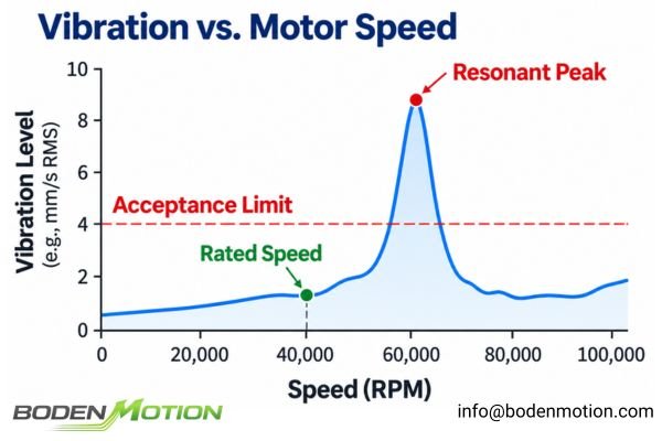
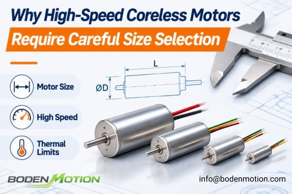
For example, a miniature high-speed motor such as the BDCL1020 coreless BLDC motor, which measures Ø10 × 20 mm and weighs 8.5 g, has winding variants with rated speeds from 39,150 to 79,640 RPM, with one version reaching a no-load speed of 88,000 RPM. Because these variants have different speed characteristics, the vibration test plan should be based on the selected winding and its intended operating conditions rather than treating a single generic test point as representative of every configuration.
The test conditions must be clearly defined, including:
- Test Speeds: Select test points that represent the minimum, rated, and maximum relevant operating speeds. Where practical, a controlled speed sweep can help identify resonant peaks within the operating range.
- Load Condition: No-load is easiest to replicate, but a defined load condition may be necessary if the application generates significant external forces.
- Supply Voltage: Must be kept constant, as voltage fluctuations can affect torque ripple and vibration.
- Temperature: The motor should be allowed to reach a stable operating temperature, as bearing preload and fit can change with heat.
- Direction of Rotation: Some asymmetries can cause vibration to differ between clockwise and counter-clockwise rotation.
It's also crucial to distinguish between steady-state vibration at a constant speed and transient vibration during acceleration or deceleration. If the application involves rapid start-stop cycles, these phases may need their own acceptance criteria.
Why Mounting Fixtures and Sensor Placement Affect the Result
Two labs can test the same motor and get wildly different results if their test setups are not identical. The fixture and sensor setup are significant sources of measurement variance.
The measurement fixture must be sufficiently stiff and mechanically stable, with a repeatable mounting arrangement, so that the test captures the motor's behavior rather than the resonance and variability of the test setup itself.
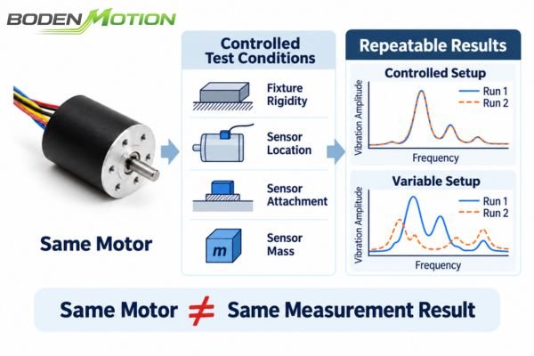
Key factors that must be standardized include:
- Mounting Fixture: The design of the fixture, its material, its mass, and the torque of the bolts used to secure the motor must be specified. A flimsy fixture can have its own resonances that amplify or mask the motor's true vibration.
- Sensor Placement: The exact location (e.g., on the front bearing housing or rear end cap) and orientation (radial or axial) of the sensor must be defined in a drawing.
- Sensor Attachment: How the sensor is attached—whether by a threaded stud, adhesive, or magnetic base—can significantly affect measurement accuracy and usable frequency range. For high-frequency measurements, a stud mount can provide good mechanical coupling when the motor geometry and sensor design allow it. The attachment method should be selected and validated for the specific test setup.
- Sensor Mass: For very small motors, the mass of the accelerometer itself can alter the vibration characteristics of the system.2 A lightweight sensor appropriate for the scale of the motor should be used.
How Frequency Range and Signal Processing Change the Vibration Result
The raw signal from a vibration sensor is a complex waveform. The way this signal is processed determines the final numerical value that is compared against the acceptance limit.
Simply stating a vibration limit in mm/s or g is meaningless without also specifying the measurement bandwidth and signal processing settings. The same motor can pass or fail based on the chosen frequency filter.
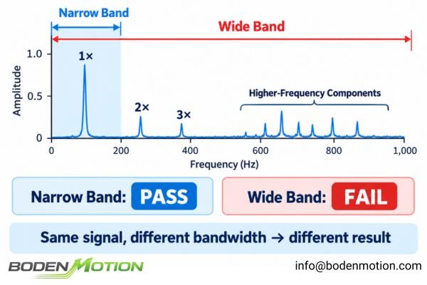
The vibration spectrum may contain a component at the motor's rotational frequency (often called 1×), which is commonly associated with rotor imbalance3.
Rotational frequency (Hz) = RPM / 60
However, the spectrum may also contain energy at harmonics of the rotational frequency (2×, 3×, etc.), at higher frequencies related to bearings and electromagnetic effects, and at frequencies corresponding to structural resonances.
The specification must define:
- Frequency Range: The bandwidth over which the vibration is evaluated (e.g., 10 Hz to 10,000 Hz).
- Filtering: Any high-pass or low-pass filters applied to the signal.
- Amplitude Convention: Whether the limit applies to the RMS (Root Mean Square), Peak, or Peak-to-Peak value of the signal.
- Data Processing: If using an FFT spectrum, the limit might apply to the amplitude of a specific frequency peak rather than the overall broadband value.
Without standardizing these settings, measurements from different tests may not be directly comparable.
How to Set an Acceptable Vibration Limit for a High-Speed BLDC Motor
Setting the right limit is a balancing act. It must be tight enough to ensure the final product works correctly, but not so tight that it is impossible to achieve in volume production.
A useful vibration limit should reflect both the motor's inherent production capability and the quantified sensitivity of the application. It should be based on data, not arbitrary numbers.
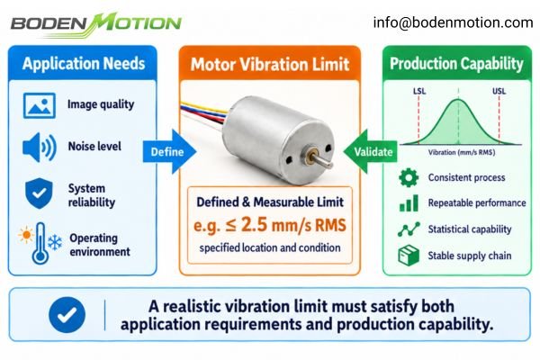
Follow this three-level approach:
- Level 1: Define Application Requirements. First, understand what the end-product needs. Does vibration cause blurry images in a scanner? Unacceptable noise in a medical drill? Premature failure in a pump? Quantify the sensitivity of the complete system.
- Level 2: Translate to a Motor-Level Limit. Based on the system-level needs, develop a specific, measurable limit for the motor itself. An illustrative example might be: "vibration velocity must not exceed 2.5 mm/s RMS at the front bearing housing, measured radially, at 40,000 RPM." This value is purely an example and not a universal standard.
- Level 3: Validate with Production Data. Test a statistically significant number of motors from a pilot production run to see if the proposed limit is achievable and repeatable4. Do not base the entire specification on one "golden sample." The limit must be achievable for a capable production process.
How to Build a Repeatable Vibration Acceptance Test
With a specification in hand, the next step is to create a formal test procedure that can be executed consistently at both the supplier's factory and the OEM's incoming quality control.
The goal of the test procedure is to eliminate as many sources of variability as possible, ensuring that any pass/fail decision is based on the motor's actual performance, not on differences in the test method.
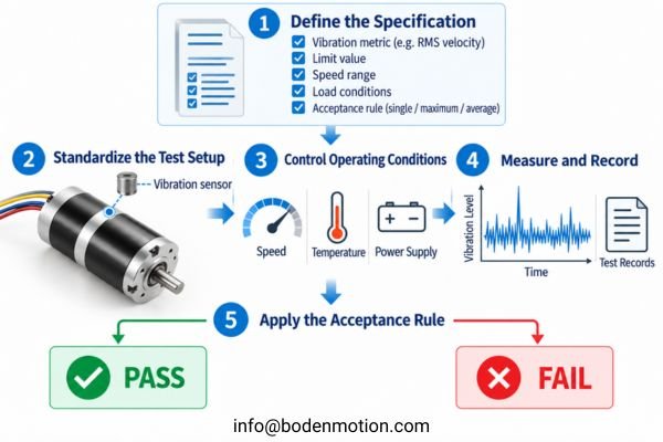
A robust procedure includes these steps:
- Define the Specification: Metric, limit, speed range, and load conditions are locked in.
- Standardize the Test Setup: Use a controlled drawing for the fixture and sensor location.
- Control Operating Conditions: Follow a strict warm-up procedure and use a calibrated power supply.
- Measure and Record: Document the results along with all test settings and equipment used.
- Apply the Acceptance Rule: The rule for pass/fail must be predefined. This could be based on a single reading, a maximum value across multiple tests, or an average. The procedure should also define how to handle borderline results or outliers to ensure consistent decisions.
This entire process should be documented in a formal test procedure that includes revision control, equipment calibration requirements, and clear rules for handling non-conforming parts.
What OEM Buyers Should Include in a High-Speed Motor Vibration Specification
To ensure clarity and avoid disputes, the vibration requirements should be a formal part of the purchasing specification provided to the supplier. This document serves as the single source of truth for acceptance.
A comprehensive specification sheet removes ambiguity, helps OEM buyers compare suppliers objectively, and reduces the risk of quality disputes during mass production.
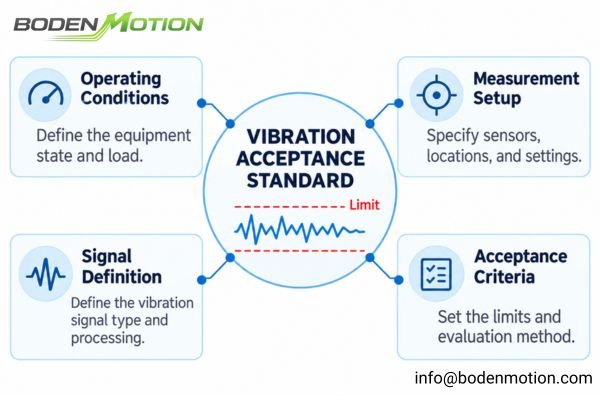
When you engage with a motor supplier, providing a detailed specification is the most effective way to communicate your needs5.
| Specification Item | Information to Define |
|---|---|
| Motor Identification | Part number and revision level |
| Operating Speed(s) | Specific RPM test points or a required speed sweep range |
| Operating Condition | No-load, or a specific, defined load and duty cycle |
| Vibration Metric | Displacement, Velocity, or Acceleration |
| Amplitude Convention | RMS, Peak, or Peak-to-Peak |
| Measurement Location | Defined point on motor housing (e.g., front flange) |
| Measurement Direction | Radial (X/Y axes) and/or Axial (Z axis) |
| Frequency Range | Required measurement bandwidth (e.g., 10 Hz – 10 kHz) |
| Mounting Fixture | Reference drawing for the test fixture and mounting method |
| Sensor | Sensor type, model, and attachment method (e.g., stud mount) |
| Signal Processing | Filter settings, averaging, or other processing parameters |
| Acceptance Limit | The numerical threshold for a pass/fail decision |
At BODENMOTION, our in-house testing resources—including load testers, power testers, environmental test chambers, and precision measuring instruments—support motor performance checks and sample validation. For projects requiring vibration acceptance criteria, we can work with OEM teams to define the required operating conditions, measurement points, and pass/fail requirements for the application.
Conclusion
A high-speed BLDC motor cannot be qualified based on a vague requirement for “low vibration.” A robust, enforceable specification must precisely identify the measured quantity, test speeds, mounting conditions, sensor position, frequency range, and numerical acceptance limit. Without this level of detail, measurements are not comparable across suppliers or production batches.
For OEM engineers, the objective is to establish a repeatable test method that accurately reflects the application's real-world requirements. By defining measurement conditions and clear pass/fail criteria before approving samples, you create a reliable quality baseline for all your future DC motor solutions and minimize disputes throughout the production lifecycle. If you are ready to discuss your project, contact our engineering team at info@bodenmotion.com.
FAQ
Q1: What is an acceptable vibration level for a high-speed BLDC motor?
There is no universal "acceptable" limit. The right level depends entirely on the motor's size and speed, the measurement method, and how sensitive the final application is to vibration. It must be defined on a case-by-case basis.
Q2: Should I measure vibration in displacement, velocity, or acceleration?
This depends on your goal. Velocity is a useful general indicator of vibration severity across a defined frequency range. Acceleration can help detect high-frequency vibration associated with bearing impacts. Displacement is useful for evaluating low-frequency oscillatory motion. If acoustic noise is the primary concern, sound pressure level should be measured separately. The chosen metric must be clearly defined in the specification.
Q3: Why can the same motor show different vibration readings on different test benches?
Differences in the mounting fixture's stiffness, fixture resonances, sensor location, sensor attachment method, and signal processing settings can all lead to dramatically different results. This is why standardizing the entire test setup is critical.
Q4: Should vibration be measured only at the motor's rated speed?
Not usually. If the motor operates over a wide speed range, testing at multiple points or performing a controlled speed sweep can help identify potential resonant frequencies where vibration could be much higher than at the rated speed.
Q5: Will a low-vibration motor guarantee a low-noise machine?
No. Motor vibration and acoustic noise are related, but they are not interchangeable. A motor with low measured vibration can still generate audible noise from electromagnetic excitation, bearings, or airflow. The mounting structure and enclosure can also introduce or amplify noise. OEM engineers should therefore evaluate acoustic noise separately under representative operating conditions rather than assuming that low motor vibration guarantees a quiet machine.
ZGBK Bearings' "7 Key Factors That Affect Bearing Life" discusses operating loads, lubrication, contamination, misalignment, and bearing quality as factors affecting bearing service life. It supports considering these conditions alongside vibration measurements, but does not establish a vibration-only lifetime prediction method. ↩
Lerche and Onari's "Modal Analysis Using Motion Magnification Methods" (2024), presented through the Texas A&M Turbomachinery Laboratory, identifies accelerometer mass loading as a measurement concern when testing small or lightweight structures. The study includes rotating machinery examples but does not specifically test miniature BLDC motors. ↩
Luis San Andrés' "Rotor Imbalance Response and Balancing of a Rigid Rotor (One Plane)" (Texas A&M University, 2019) models the synchronous response caused by rotor mass imbalance and illustrates its dependence on rotational speed. This supports the association with a 1× vibration component, which is not by itself unique to imbalance. ↩
1Factory's "Process Capability Analysis Cp, Cpk, Pp, Ppk - A Guide" explains how initial production measurements can be used to assess whether a stable manufacturing process can consistently meet specification limits. It does not prescribe a universal pilot-run sample size or motor-vibration acceptance limit. ↩
The Government of South Australia's "Developing a Specification Guideline" (Procurement Services SA, Version 1.1, effective February 20, 2023) emphasizes clear and accurate procurement requirements, including technical, performance, and quality criteria, so suppliers understand what is required. It does not establish that a specification is more effective than every other communication method. ↩