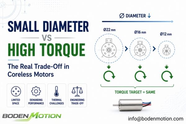
"Can you make the motor smaller but keep the same torque?" This is a frequent and understandable request in the world of compact OEM devices.
A miniature coreless motor can produce high peak torque for short durations, but its continuous torque is fundamentally limited by thermal dissipation, creating a critical trade-off between size, sustained output, efficiency, and lifetime.
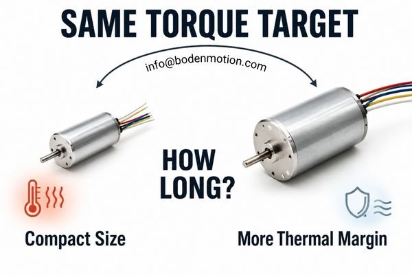
Coreless motors are appealing for their excellent torque-to-inertia ratio in a lightweight package1. However, the pursuit of miniaturization while demanding high torque runs into the hard limits of physics. Torque capability isn't just one number on a datasheet; it's a dynamic balance of motor diameter, length, magnetic design, current, speed, duty cycle, and, most importantly, thermal management. The real engineering question is not "Can it be smaller and stronger?" but rather, "How much torque is required, at what speed, for how long, and inside what thermal and physical envelope?"
What Does Torque Density Mean in a Coreless Motor?
The term "torque density" is often used as a benchmark for performance, but without proper qualification, it can be misleading and lead to design failures.
Torque density measures torque relative to a motor's size or mass, but it is important to distinguish between peak torque density, which is primarily constrained by short-term current and electromagnetic limits, and continuous torque density, which is constrained by steady-state thermal capability.
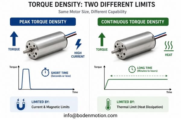
In any OEM project, we have to break this concept down into two distinct categories, as they are governed by different physical limitations.
Peak Torque Density
This reflects a motor's ability to deliver high torque for very short periods, typically seconds or less. It is primarily a function of electromagnetic and electrical limits, such as the peak current from the driver, the motor's torque constant (Kt), and the strength of the magnetic circuit. It is most relevant for overcoming static friction, rapid acceleration, or short, high-force clamping actions.
Continuous Torque Density
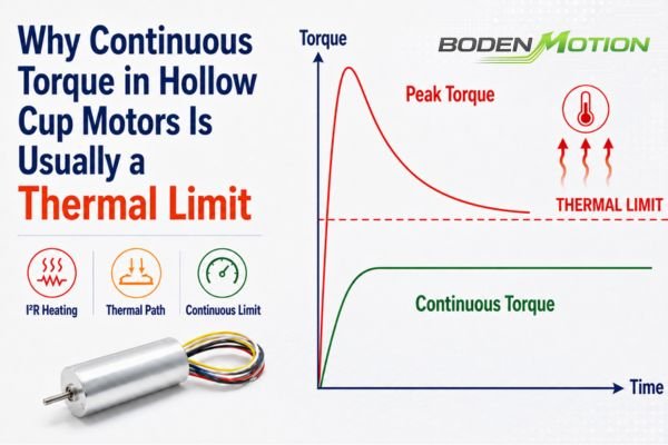
This measures the torque that can be sustained at thermal equilibrium without exceeding the specified winding-temperature limit under defined ambient, mounting, and cooling conditions. It is governed by thermal properties, including the motor's thermal resistance and heat dissipation path. This is the critical parameter for pumps, fans, or any application with a long duty cycle.
How Motor Diameter and Length Shape Torque Potential
Once peak and continuous torque density are separated, the next question is how much torque capability can realistically fit inside the available motor envelope. For compact OEM systems, both diameter and length matter, but they influence the design in different ways.
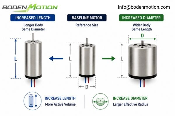
Motor diameter and active length together define much of the motor's available electromagnetic and thermal design space. Increasing diameter expands the effective electromagnetic radius and radial design space, while increasing length can add winding and active magnetic volume when radial space is fixed.
Why Diameter Matters
Diameter has a particularly strong influence on torque potential because it affects the effective radius at which electromagnetic force acts.2 A larger diameter also provides more radial design space for the winding, magnetic circuit, mechanical structure, and thermal integration.
This can be illustrated by comparing two BODENMOTION graphite-brushed coreless platforms with similar lengths but different diameters:
- The BDCB1626 graphite-brushed coreless DC motor (Ø16 × 26 mm) offers a nominal torque range of approximately 2.71–3.64 mN·m.
- The BDCB2225 22 mm coreless motor (Ø22 × 25 mm) offers a nominal torque range of approximately 3.67–6.24 mN·m.
These figures do not establish a universal diameter-scaling law because winding, magnetic, speed, current, and thermal designs differ between platforms. They do, however, illustrate why additional radial space gives the motor designer more freedom to build torque capability into a compact motor.
When Length Is the Available Design Lever
In many OEM devices, however, diameter is already fixed by the surrounding housing. In that case, increasing motor length can be another way to expand the available design envelope without requiring more radial space.
A longer motor can provide additional winding volume and active magnetic length, increasing the electromagnetic volume available for torque and power production. It also increases thermal capacity, although sustainable continuous output still depends on winding losses and the actual heat-dissipation path.3
BODENMOTION's Ø17 mm graphite-brushed platforms illustrate this second design direction:
- The BDCB1725 (Ø17 × 25 mm) is rated for a nominal torque of 3.28–3.81 mN·m.
- The BDCB1740 17 mm hollow cup motor (Ø17 × 40 mm) reaches a nominal torque of 6.0–9.8 mN·m.
Again, this should not be treated as a controlled length-only comparison because the internal motor configurations may differ. The useful engineering lesson is that diameter and length are two different packaging levers: radial space can expand the electromagnetic radius, while axial space can provide additional active motor volume.
When neither diameter nor length can be increased, current often becomes the next lever engineers consider for obtaining more torque—but that introduces a much steeper thermal trade-off.4
Why Increasing Current Can Raise Torque—but Only to a Point
When a small motor's torque is insufficient, the most intuitive fix is to increase the current. This works, but it comes with a steep and often underestimated thermal penalty.
Within the motor's usable linear electromagnetic operating range, torque increases approximately in proportion to torque-producing current (T ≈ Kt × I), while copper loss increases with the square of current (Pcu = I²R).
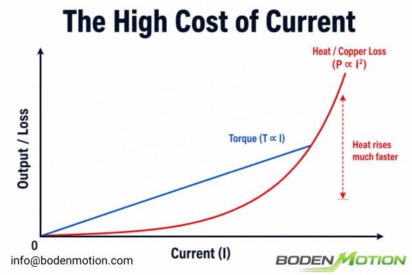
This relationship is why small motors can achieve impressive peak torque for brief moments. The problem is that the current flows through the resistive winding, generating heat. Consider a simple illustrative example:
- At 0.5 A, copper loss is
(0.5)²R = 0.25R. - At 1.0 A, copper loss is
(1.0)²R = 1.00R.
Doubling the current approximately doubles the electromagnetic torque within the usable linear range, but quadruples the copper loss that must be managed thermally. This is why a prototype that works during short tests may exceed its thermal limits during continuous operation inside its final enclosure. In a real motor, performance is further limited by winding temperature, driver current limits, commutation, and magnetic saturation.
Peak Torque vs Continuous Torque in a Miniature Coreless Motor
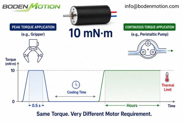
A request for "10 mN·m of torque" is an incomplete specification. The critical follow-up question is, "For how long?" The answer completely changes the motor selection.
Peak torque is for short-duration tasks limited by current and commutation, while continuous torque is for sustained operation and is limited by the motor's ability to dissipate heat and maintain thermal equilibrium.
Let's compare these two distinct requirements:
| Requirement Factor | Peak Torque | Continuous Torque |
|---|---|---|
| Typical Duration | Milliseconds to seconds | Sustained / steady-state operation |
| Main Electrical Factor | Peak current (I_peak) |
RMS current (I_rms) |
| Primary Limitation | Driver current, commutation, magnetic saturation | Winding temperature limit, thermal path5 |
| Thermal Impact | Limited accumulation due to short duration | Thermal equilibrium is critical |
| Relevance | Startup, acceleration, intermittent pulses | Constant-speed operation, long duty cycles |
| Lifetime Impact | Stress depends on repetition frequency | Strongly linked to operating temperature |
Consider two real-world scenarios:
- Application A: Robotic Gripper: Needs a high closing force for 0.5 s. A small motor driven with a high current pulse can generate the necessary peak torque, and the long "off" time between actuations allows it to cool.
- Application B: Miniature Peristaltic Pump: Needs to run for hours at a constant torque. The same motor could overheat in this continuous operation if its RMS current and thermal path exceed its continuous limits. A larger motor, improved thermal path, or different operating point may need to be evaluated.
Why Chasing Maximum Torque Density Can Reduce Efficiency and Lifetime
Focusing solely on extracting the absolute maximum torque from the smallest possible motor is a dangerous path. It often degrades overall system performance and reliability.
Pushing a small motor to its torque limit via extreme current density leads to lower efficiency, reduced thermal margin, increased stress on the driver and wiring, and a potential reduction in motor lifetime.
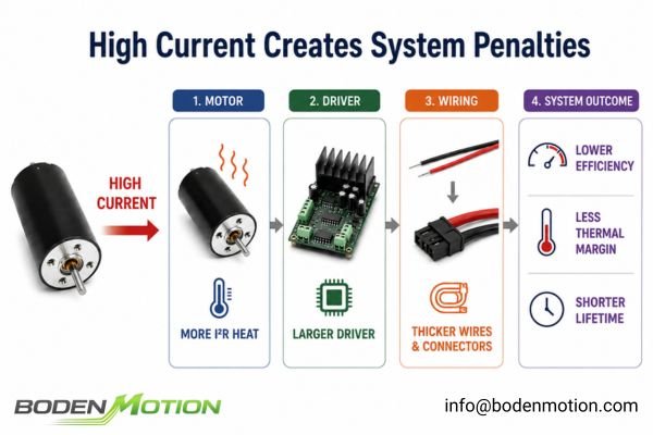
Attempting to operate a motor continuously in its peak torque region introduces several system-level problems beyond just heat:
- Drastically Lower Efficiency: A motor's efficiency is not constant. Operating at very high currents pushes the motor into a low-efficiency region where a large fraction of the input power becomes waste heat.
- Stressed Electronics: A high-current motor demands a high-current driver, which may require larger MOSFETs and better heat sinking, canceling out the size savings of the motor.
- Wiring and Connection Issues: High current necessitates thicker-gauge wires and higher-rated connectors to prevent significant voltage drops and overheating.
- Reduced Lifetime: Sustained high temperatures can degrade winding insulation, break down bearing lubricant, and, in brushed motor designs, accelerate wear of the brush-commutator system.
System-Level Observation: Maximum torque density is not necessarily the optimum system design. A well-designed system prioritizes a balance of performance, efficiency, reliability, and thermal margin.
What OEM Buyers Should Provide for High-Torque Coreless Motor Matching
To help us select the right motion solution, the inquiry needs to go beyond a simple size and torque value. A complete load profile is essential.
Instead of asking for a generic "high-torque motor," OEM engineers should provide a complete operating profile including dimensions, torque levels, speed, duty cycle, and thermal conditions.
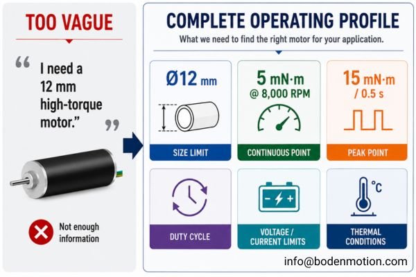
A useful requirement moves from "I need a high-torque 12 mm motor" to "We need 5 mN·m continuously at 8,000 rpm, with 15 mN·m for 0.5 s during startup, inside a 12 mm diameter." A comprehensive inquiry should include:
- Mechanical Envelope: Max diameter and length.
- Continuous Operating Point: Continuous torque and corresponding RPM.
- Peak Operating Point: Peak torque, its duration, and corresponding RPM.
- Motion Profile & Duty Cycle: Startup/acceleration needs, cycle frequency, on/off times.
- Electrical Platform: Voltage range and driver current limits (continuous/peak).
- Thermal Environment: Ambient temperature, enclosure type, mounting structure (metal/plastic).
Across BODENMOTION's coreless motor platforms, a wide range of capabilities exists, illustrating why detailed requirements are necessary.
| Motor Type | Diameter | Length | Nominal Torque | Nominal Current |
|---|---|---|---|---|
| Precious Metal Brushed | 12–28 mm | 18–54 mm | 0.90–27.47 mN·m | 0.07–1.90 A |
| Graphite Brushed | 16–40 mm | 25–71 mm | 2.71–196.86 mN·m | 0.19–12.09 A |
| Coreless Brushless | 10–50 mm | 18–100 mm | 0.32–668.79 mN·m | 0.10–32.65 A |
These ranges should not be interpreted as a direct size-to-torque scaling rule, as the values come from different motor platforms, windings, lengths, and speeds. The data illustrates why diameter alone is not enough information for proper motor selection.
When Should You Use a Larger Motor—or Add a Gearbox Instead?
When a miniature motor cannot meet the continuous torque requirement without overheating, simply trying to find a "stronger" motor of the same size is often futile. The next step requires a system-level decision.
If a small motor is thermally limited, the solution may be a larger motor for better thermal margin, or adding a gearbox to provide higher output torque at a reduced output speed.
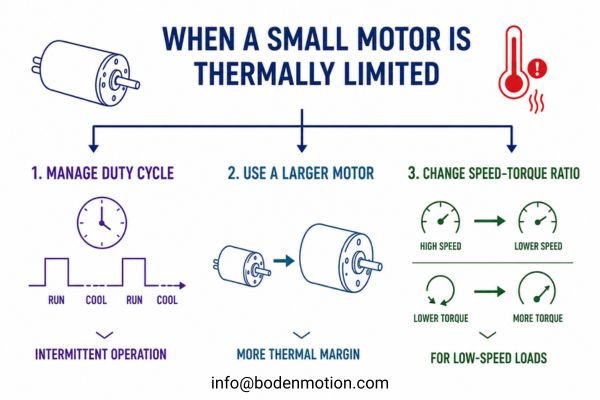
Here are the three primary paths forward:
- Keep the Small Motor and Manage the Duty Cycle: Viable only for intermittent applications with sufficient cooling time.
- Increase the Motor Size: Increasing diameter or length is the most direct way to gain both electromagnetic capability and thermal margin for higher continuous torque6.
- Add a Gearbox: Often the most sensible solution for high-torque, low-speed applications. It allows the motor to run at a higher, more efficient speed. However, this introduces trade-offs like efficiency loss, backlash, noise, added size, and cost.
Conclusion
Small diameter and high torque can coexist in a coreless motor, but only within strict electromagnetic, thermal, and duty-cycle limits. While high current can produce impressive short-term torque, heat becomes the dominant boundary for continuous operation. The optimal solution balances motor size, torque, speed, current, and thermal margin. The correct answer may be a different motor size, a longer active length, a more suitable winding, or a properly selected gearbox—not just a search for an unrealistically "stronger" motor of identical dimensions.
For your next compact OEM project, provide us with your complete operating point: max dimensions, continuous torque and RPM, peak torque and duration, voltage and current limits, and thermal conditions. Our engineering team can help evaluate these trade-offs and find a balanced motion solution. Contact us at info@bodenmotion.com.
FAQ
Q1: Can a small coreless motor produce high torque?
Yes, particularly for short periods (peak torque) when sufficient current is available. Continuous high torque is more challenging because heat dissipation becomes the limiting factor.
Q2: Does increasing current always increase torque?
Within the motor's linear operating range, torque is roughly proportional to current. However, current cannot be increased indefinitely due to thermal limits (I²R losses), driver capacity, and eventual magnetic saturation or commutation limits.
Q3: Does increasing motor diameter always increase torque?
A larger diameter provides a larger design envelope for torque production, but it does not guarantee higher torque. Actual performance depends on the complete design, including length, winding, magnets, and operating conditions.
Q4: Can I keep the same diameter and use a longer motor to get more torque?
Yes. Increasing motor length can increase active electromagnetic and winding volume, making it an important design lever when radial space is constrained. The actual increase in continuous torque still depends on winding design, operating current, speed, and heat dissipation.
Q5: When should I consider a gearbox?
A gearbox is a strong candidate when your application requires high output torque at a low output speed. It allows the motor to operate at a higher, more efficient speed while delivering the required torque at the output, but introduces its own system trade-offs.
Servotecnica, "What are the coreless motors?" The article explains that coreless motors combine low rotational inertia with high torque capability, compact dimensions, and low weight, supporting their suitability for high-dynamic applications. ↩
ROHM TechWeb, "An Introduction to Motors." The motor fundamentals guide explains that torque depends on both the applied force and its distance from the axis of rotation, so increasing the effective radius increases torque for the same force. ↩
E-Mobility Engineering, "Thermal Management in Electric Vehicles: E-Motor Cooling Technology." The article discusses motor thermal mass, winding-generated heat, thermal resistance, and the heat-transfer paths from windings and other active components to the housing and cooling system, showing why continuous output depends strongly on effective heat dissipation. ↩
Pulse Motor, "Heat Generation of a Motor and a Driver." The engineering guide explains that increasing motor current can increase available torque, while winding copper loss rises with the square of current, creating a rapidly increasing thermal burden at higher current levels. ↩
"Selecting a DC Micromotor," PT Design / MicroMo Electronics. The guide identifies temperature as a primary constraint on DC micromotor operation and relates winding copper loss, coil-to-ambient thermal resistance, temperature rise, and maximum permissible coil temperature when evaluating continuous operation. ↩
Monolithic Power Systems, "General Properties of Electric Motors." The motor design guide explains that smaller motors have less space for windings and magnetic materials, while larger motor sizes can provide greater electromagnetic design space and improved heat-dissipation capability. It also emphasizes the connection between cooling, allowable current density, torque density, and thermal limits. ↩