A coreless brushed motor may be rated for thousands of operating hours, but that number does not automatically predict its life in every application. Brush wear is not a simple function of time; it is an accumulation of electrical and mechanical stress at the brush-commutator interface. For OEM engineers specifying coreless motors, understanding these wear mechanisms is essential when evaluating motor reliability under actual operating conditions.
Motor operating hours describe elapsed running time; brush life depends on the accumulated contact stress during those hours. Two motors of the same model can have substantially different operational lifetimes depending on their current load, speed, and duty cycle.

The engineering question is therefore not simply how long a motor runs, but what electrical and mechanical stress its brush system experiences1 throughout that time. Understanding these factors is critical for accurately forecasting reliability in a real-world OEM application.
How Brush and Commutator Wear Occurs in a Coreless Brushed Motor
In a coreless brushed DC motor, the self-supporting, ironless winding rotates with low rotor inertia. The brushes must maintain continuous contact with the commutator segments to energize the winding. At this interface, wear results from a combination of mechanical sliding and electrical current transfer.
Brush lifetime is determined by the complex interaction between mechanical friction and electrical phenomena. It is not a single failure mechanism but a combination of gradual wear and event-driven damage, with severity depending on motor design and application conditions.

We can break down the wear mechanisms into two main categories:
- Mechanical Wear: This is caused by the physical sliding of the brush against the rotating commutator. Key factors include the contact force exerted by the brush spring, the sliding speed (related to motor RPM), the surface finish of both materials, and mechanical vibration.
- Electrical Wear: This results from the flow of current across the contact interface. It includes resistive heating at microscopic contact points, material transfer between the brush and commutator, and electrical arcing that can occur during commutation as the brush moves from one segment to the next.
Even at low currents, mechanical sliding causes gradual wear. At higher currents or under adverse switching conditions, electrical wear can become the dominant and life-limiting factor.2
Why Higher Current Density Can Accelerate Brush Wear
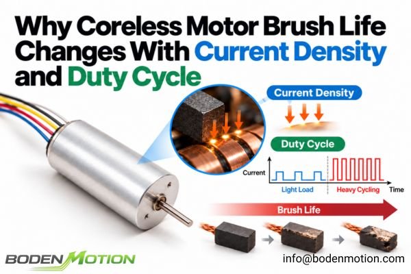
Higher current can increase brush wear, but contact current density helps explain what happens at the microscopic contact interface. The electrical current does not flow uniformly through the entire brush face; it concentrates through a small and ever-changing number of microscopic conductive spots.
Total motor current matters, but contact current density helps describe the electrical loading of the actual conductive spots. Brush wear also depends on materials, contact pressure, commutation behavior, temperature, and mechanical conditions.

Conceptually, contact current density can be expressed using a simplified relationship:
Here, J is contact current density, I is the current flowing through the contact interface, and Aeff is the effective conductive contact area. The effective area changes as the microscopic contact spots form and separate, making it difficult to determine directly in an operating motor. This relationship explains the local concentration of current; it is not a practical formula for predicting brush life.
A higher current density can lead to:
- Localized Heating: Intense heat generated at tiny contact spots can degrade the brush and commutator materials.
- Increased Electrical Stress: High densities can accelerate material migration and electrical erosion.
- Contact Degradation: Over time, this stress can change surface properties, increase contact resistance, and lead to unstable performance.
The same terminal current may therefore produce different contact stresses in different brush systems. Contact geometry, material properties, surface condition, and mechanical friction must be considered alongside electrical loading.
How Commutation Events and Switching Waveforms Affect Contact Damage
Brush wear is heavily influenced by the dynamic events of commutation. In a coreless motor, the low-inductance winding allows for very rapid current changes. As the commutator rotates beneath the brushes, current is transferred between segments and the current in individual winding sections is commutated.
Brush wear depends not only on current magnitude but also on how current changes during commutation and electronic driving. Lower winding inductance can reduce inductive energy involved in mechanical commutation, yet it can also allow greater PWM current ripple under otherwise comparable drive conditions.

The magnetic energy stored in an inductive winding can be expressed as:
Here, E is stored magnetic energy, L is inductance, and I is winding current. At the same current, a lower effective inductance means less stored energy that could contribute to arcing during mechanical commutation. Actual contact damage still depends on commutation geometry, materials, and switching conditions. The same low inductance also permits faster current changes in response to applied voltage, which can increase PWM current ripple if the driver is not appropriately configured.
This doesn't mean PWM is inherently bad for brushes. It means the PWM frequency, supply voltage, and drive topology must be well-matched to the motor to manage this ripple. A poorly configured driver can produce substantial current ripple and repeated current peaks, increasing contact stress even if the average current appears low.
The duty cycle of PWM switching should also be distinguished from the application's operating duty cycle. PWM duty cycle controls the proportion of each switching period during which voltage is applied, while the broader operating duty cycle describes how the motor runs, stops, and repeats its working sequence.
Why Average Current Alone Cannot Describe Brush-Life Stress
OEMs often specify a motor's load in terms of average current. Average current can help describe the overall loading profile, but it cannot by itself describe resistive heating or brush-wear risk because it conceals peaks, current ripple, and off-time intervals.
Two applications can have identical average current over a complete cycle but different RMS currents and peak currents. RMS current helps assess resistive heating, while peak magnitude, peak duration, and commutation conditions help characterize potential stress at the brush contacts.
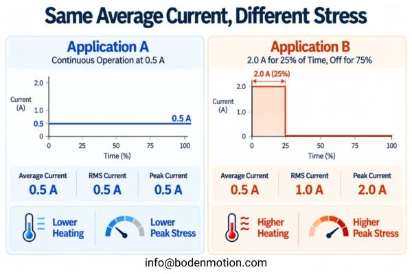
Consider two idealized duty cycles for the same motor over the same observation period. Startup and shutdown transients are omitted here to focus on the basic current profiles:
-
Application A: Runs continuously at 0.5 A.
- Average Current = 0.5 A
- RMS Current = 0.5 A
-
Application B: Runs at 2.0 A for 25% of the time and is off for 75%.
- Average Current = (2.0 A × 0.25) + (0 A × 0.75) = 0.5 A
- RMS Current = √(2.0² × 0.25) = 1.0 A
Both applications have the same average current over the full observation period, including off-time. However, Application B has twice the RMS current. At equal winding resistance, this corresponds to four times the time-averaged resistive loss, although actual temperature rise also depends on thermal dynamics and cooling during the off-time5. For the brushes, Application B also produces 2.0 A running-current intervals rather than a steady 0.5 A. These different waveforms imply different potential wear mechanisms, but they do not establish a numerical brush-life ratio.
How Motor Speed, Start–Stop Cycles, and Reversing Change Brush Wear
The mechanical aspects of the duty cycle are just as important as the electrical ones. Operating hours alone do not reveal the accumulated revolutions, number of starts, or direction changes the motor has undergone.
Equal operating hours do not necessarily mean equal revolutions, current peaks, or contact-stress events. The motion profile and the way the driver controls it both influence mechanical and electrical wear.
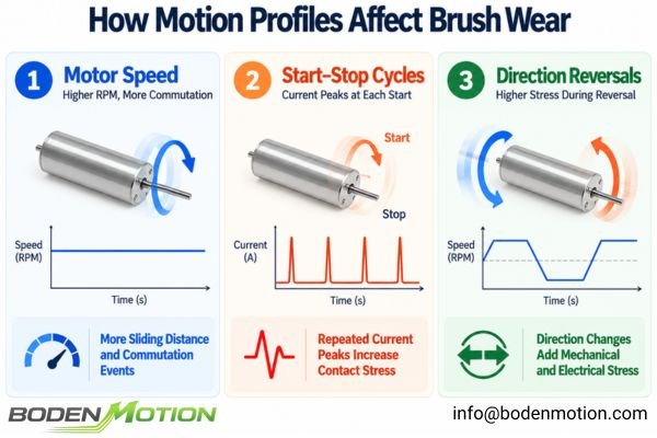
- Motor Speed (RPM): Higher speed increases the sliding distance per minute and the number of commutation events per second. This directly influences the rate of mechanical wear and the frequency of electrical switching stress.
- Start–Stop Cycles: A direct-on-line startup can cause a high inrush current. However, a modern driver using current-limiting or controlled acceleration can significantly reduce this peak. The risk from frequent starting depends on the actual current peak, its duration, and the repetition frequency.
- Direction Reversals: Rapidly reversing a motor can be stressful, but the severity depends on the control strategy. An aggressive reversal with plug braking creates high currents, while a controlled ramp-down and ramp-up sequence is far gentler on the brush contacts.
| Operating Condition | Continuous Light-Load Operation | Frequent Start–Stop / Reversing |
|---|---|---|
| Running Current | Relatively stable | Can be highly variable with peaks |
| Mechanical Wear | Accumulates with sliding distance and depends on contact conditions | Depends on sliding distance, contact conditions, and dynamic loading |
| Electrical Stress | Lower, steady-state | Depends on driver control of transients |
| Main Lifetime Concern | Accumulated sliding/contact wear | Combined transient and running stress |
Why Brush Material and Operating Environment Change the Wear Mechanism
The principles of current density and duty cycle apply to all brushed motors, but the specific outcomes depend heavily on the brush materials and the environment. It is a common mistake to apply rules for one brush type to another.
Brush-life evaluation must consider the specific contact material and operating environment. Precious-metal and graphite-based brush systems have different wear mechanisms and sensitivities.
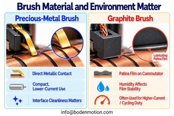
- Graphite Brush Systems: These brushes often rely on the formation of a "patina"—a lubricating film on the commutator surface that can contain graphite, copper oxides, and moisture-related constituents6. The stability of this film can be sensitive to humidity. In very dry environments, the lubricating conditions may deteriorate, potentially increasing friction and mechanical wear.
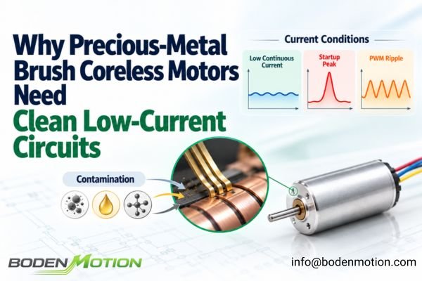
- Precious-Metal Brush Systems: Common in smaller coreless motors, these systems use precious-metal contact alloys. Unlike graphite systems, they do not depend on the same humidity-sensitive surface film. Their performance depends on contact mechanics, electrical erosion, lubrication where applicable, and the cleanliness of the commutator interface.
In general, graphite-based and precious-metal brush systems are suited to different operating priorities: graphite-based designs are often better suited to higher current loads and frequent start-stop or reversing duty, while precious-metal contacts are commonly used in compact, lower-current applications7. These are selection tendencies rather than universal limits; the specific motor design and test conditions remain decisive. Operating temperature, humidity, and contaminants should therefore be evaluated for the selected brush system.
How to Convert a Real Duty Cycle Into a Brush-Life Test Profile
Explaining wear factors is useful, but for an OEM engineer, the practical goal is to create a test profile that supports a credible lifetime assessment for the final product.
A brush-life test is valuable only when its electrical and mechanical stress profile represents the intended application, or a validated acceleration model connects the two. Extrapolation without a model is risky.
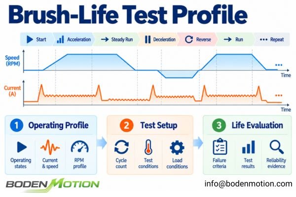
To create a representative test, follow these steps:
- Define Operating States: Map out a complete cycle: startup, acceleration, steady run, deceleration, stop, reversal.
- Record Current and Speed: Measure the current waveform, peak current, and RPM for each state using the actual application driver.
- Count Repeated Events: Quantify the number of starts, stops, and reversals per hour or day.
- Define Test Conditions: Standardize the supply voltage, ambient temperature, and mechanical mounting.
- Establish End-of-Life Criteria: "Failure" is rarely a simple "motor stops turning." The criteria must be application-specific. For example, a failure could be defined as when the no-load current increases by 50% (an illustrative example, not a universal standard), the start-up voltage exceeds a certain threshold, or speed regulation degrades beyond an acceptable limit.
- Analyze Test Results: Compare the number of completed cycles on test to the target application life, recording sample size, failures, and test duration so the reliability evidence can be interpreted appropriately.
What OEM Engineers Should Provide for Brush-Life Risk Evaluation
To get a meaningful lifetime assessment from a motor supplier, you must provide a detailed picture of your application's duty cycle. A simple "I need a motor that lasts 2,000 hours" is not enough information for a proper engineering evaluation.
The correct brush system should be matched to the real duty cycle—not selected from a catalog lifetime number or brush material name alone.

Use this checklist to define your requirements for a supplier discussion:
| Factor | Information OEM Should Provide | Why It Matters for Supplier Evaluation |
|---|---|---|
| Continuous Current | Typical operating current during steady run | Sets the baseline electrical and thermal load |
| Peak Current | Maximum transient current (e.g., at startup) | Defines the peak electrical stress on contacts |
| Peak Duration | How long the peak current lasts | Determines the duration of high-stress events |
| Current Waveform | Oscilloscope capture of the motor current | Reveals ripple and actual driver switching behavior |
| Operating Speed | Typical RPM range | Governs mechanical sliding and commutation frequency |
| Start/Stop Frequency | Starts or cycles per hour/minute | Quantifies repeated transient stress events |
| Reversing Frequency | Direction changes per cycle | Indicates potentially demanding dynamic current conditions |
| Duty Cycle | On-time and off-time intervals | Affects thermal accumulation and cooling |
| Environment | Ambient temperature, humidity, known contaminants | Influences contact surface chemistry and wear mechanism |
| Lifetime Target | Desired operating hours and/or total cycles | Sets the validation goal for testing and selection |
| Failure Definition | Allowable performance degradation (e.g., speed drop) | Provides a clear, measurable end-of-life point |
When you contact a motor supplier, share your motor current profile, start–stop frequency, operating speed, and lifetime target. This allows their engineering team to properly evaluate the brush-contact operating conditions8 and identify potential reliability risks in your application.
Conclusion
Brush life in a coreless brushed motor depends on more than accumulated operating hours. Electrical contact stress, mechanical sliding, commutation behavior, motor speed, and environmental conditions all contribute to how brush and commutator surfaces wear over time. Higher current density and unfavorable switching conditions can increase contact damage, while frequent startups, reversals, and changing loads create a substantially different operating profile from steady light-load running.
For OEM engineers, brush-life evaluation should therefore begin with the actual current waveform and mechanical duty cycle. Continuous current, peak magnitude and duration, accumulated revolutions, switching behavior, operating temperature, and acceptable performance degradation should be considered together. A lifetime claim becomes meaningful when its test conditions and failure criteria are sufficiently representative of the final application. By sharing your detailed duty cycle, our engineering team can help you assess these risks; contact us at info@bodenmotion.com to discuss your application.
FAQ
Q1: Does higher current always reduce coreless motor brush life?
Under otherwise comparable conditions, higher current can increase contact heating and electrical erosion, potentially accelerating wear. However, the actual impact depends on the brush material, contact current density, current waveform, and duration of the peak, not just the magnitude.
Q2: Do precious-metal brushes and graphite brushes wear the same way?
No. They have different wear mechanisms and operating sensitivities. Graphite brushes often depend on a humidity-sensitive lubricating surface film, while precious-metal brushes have different contact and lubrication characteristics. Both systems can be affected by electrical loading, mechanical wear, and environmental contamination.
Q3: Is average current a good way to estimate brush wear?
No. Average current can hide short-duration peaks and substantial PWM current ripple, both of which may increase brush-wear risk. Evaluating peak current, RMS current, and the full current waveform provides a more useful picture of electrical and thermal stress.
Q4: Why can frequent start-stop operation be worse than continuous running?
Repeated startups can introduce high inrush currents and thermal cycling. The accumulated stress from many transient events can cause more wear than an equivalent number of hours in steady, light-load operation, depending on how the driver controls the current.
Q5: Does the low inductance of a coreless motor make it immune to brush damage from PWM?
No. While low inductance can reduce arcing during mechanical commutation, it can also lead to higher current ripple from a PWM driver. The drive frequency and control strategy must be properly matched to the motor to manage this ripple and reduce brush-wear risk.
Q6: What is the most critical information to provide for a brush-life evaluation?
Provide the complete duty cycle: a current waveform capture from the actual application, operating voltage and speed range, the frequency of starts/stops and reversals, environmental conditions, and a clear, application-specific definition of "end-of-life."
Li, Feng, Wang, and Xu, "Experimental Study and Numerical Analysis of Vacuum Thermal Characteristics of Brush DC Motor," *Energy Storage and Saving* (2023), examine mechanical friction and electrical erosion as contributors to brush–commutator heating through modeling and experiments under vacuum conditions. The study does not establish a general lifetime-prediction model for miniature coreless motors. ↩
Robert J. Hamilton, "Brush Life in DC Motors," *Plant Services* (1997), discusses how current loading, poor commutation, and increased sparking contribute to electrical erosion and shorter brush life. The discussion concerns industrial carbon-brush DC motors; its wear factors are not universal values for miniature coreless motors. ↩
Wikipedia, "Current Density," defines current density as electric current per unit cross-sectional area. Here, J = I / Aeff is used as a conceptual average over the effective conductive brush contact area, not as a validated brush-wear or service-life prediction equation. ↩
Wikipedia, "Inductor," derives E = ½LI² for magnetic energy stored in an inductor of constant inductance. This relationship does not establish how much energy is actually dissipated in a brush–commutator arc. ↩
Oriental Motor, "Temperature Rise and Life of an AC Motor," explains how intermittent operation, stop intervals, and heat dissipation affect motor temperature rise. Its examples concern AC motors, not the brush-contact temperature or lifetime of miniature coreless brushed motors. ↩
Ulrich Ringleb, "Carbon Ceramics for Current Transfer," *Wind Systems* (2012), describes the protective patina on carbon-brush/slip-ring contacts as containing graphite, moisture, and oxides of the ring material. The source concerns slip rings rather than segmented DC motor commutators and does not establish that copper oxides are present in every such contact film. ↩
Angelica Perzan, "Precious Metal vs. Graphite Brushes," maxon (2024), explains why graphite brushes are often preferred for demanding start–stop and bidirectional duty with high current peaks, while precious-metal brushes are often used in lower-current continuous-running applications. These are application-dependent selection tendencies, not universal current or lifetime limits. ↩
Zhao et al., "Mathematical Model of Contact Resistance for Brush and Slip Ring System Considering the Impact of Marine Environment," *Sensors* (2025), investigate the effects of contact current, pressure, sliding speed, and salt spray concentration on contact resistance in a carbon-brush/slip-ring system. The results support considering brush-contact operating conditions but do not directly predict brush life in miniature segmented-commutator motors. ↩