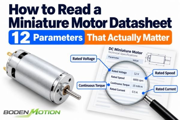
A miniature motor datasheet may contain dozens of electrical, mechanical, and thermal specifications. However, not every parameter carries the same weight. A motor for a portable medical device may be constrained by power consumption and noise, while one for an automation mechanism may depend more on continuous torque and acceleration. Simply choosing the motor with the highest speed or torque can lead to a design that is oversized, inefficient, or unreliable.
A motor datasheet becomes a useful selection tool only when its specifications are connected to the actual operating conditions and engineering decisions of the application. A datasheet tells you what has been specified or measured under defined conditions; it does not automatically guarantee the same performance in your system.
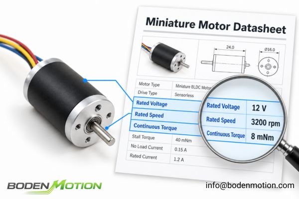
The correct approach is to evaluate specifications in a practical sequence that mirrors the integration process: from electrical compatibility and mechanical output to thermal limits, physical integration, and finally, reliability evidence.
How to Identify the Motor Type and Datasheet Test Boundary
Before diving into the numbers, it is critical to understand what kind of motor the datasheet describes and what the numbers represent. Different motor architectures and specification standards make direct comparisons between suppliers challenging.
Before comparing motor specifications, confirm that the datasheets describe equivalent equipment and measurement conditions. A simple parameter like "rated current" can have different meanings for a brushed motor versus a complete brushless motor and driver system.
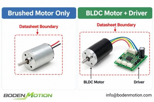
First, identify the motor architecture:
- Is it a brushed (coreless or conventional) or brushless (slotted or slotless) DC motor1?
- Does the datasheet describe the motor alone, or a motor-gearbox, motor-encoder, or motor-driver combination?
- For a BLDC motor, does "current" refer to the DC input to the driver or the AC phase current in the windings?
Next, identify the specification boundary:
- Are the values nominal (typical), guaranteed minimum/maximum limits, or simply theoretical calculations?
- Were the tests performed at a standard ambient temperature (e.g., 22 °C) or at an elevated temperature?
- Does a performance curve apply to a specific part number or a general motor family?
Which Electrical Input Parameters Should Be Checked First?
Starting with the electrical input parameters is logical. If the motor is not compatible with the available power supply and driver, its mechanical performance is irrelevant.
Rated voltage is a reference operating condition, not a complete definition of the allowable supply range. The first step is to ensure the motor's voltage and current requirements are compatible with what your system can safely and reliably provide.
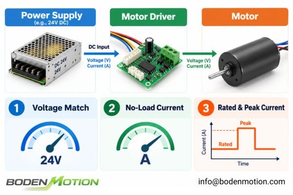
1. Rated Voltage and Operating Voltage Range
This is the fundamental compatibility check. The motor's operating voltage range must align with your system's power supply, accounting for any tolerances or battery voltage sag under load. Operating a 24V motor at 18V may restrict the achievable speed-torque range, but the actual performance depends on the load and control strategy.
2. No-Load Current2
This is the current the motor draws at its rated voltage with no external mechanical load. It is an indicator of internal friction, as well as electrical losses. Winding resistance is also important because, together with winding current, it determines copper losses through I²R heating. These losses should be evaluated under the actual operating conditions, using the appropriate RMS current where applicable.
3. Rated and Peak Current
The datasheet will often list a rated (continuous) and a peak (intermittent) current. The engineering question is: can the power supply and driver deliver the required current? A motor may require a high peak current to overcome inertia and accelerate, and if the driver's current limit is too low, the motor will fail to perform. Winding inductance influences how quickly the current responds to the driver, which is especially important for managing current ripple in low-inductance coreless motors driven by PWM.
How to Interpret No-Load Speed and Rated Operating Speed
Speed is one of the most frequently misunderstood specifications. The large "no-load speed" number is often attractive, but it rarely reflects the motor's performance in a real-world application.
A motor's no-load speed is an unloaded reference point measured at a specific voltage. The rated speed, which is specified at a defined load torque, is a far more useful indicator of performance in an actual application.
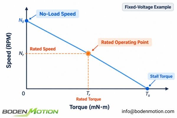
4. No-Load Speed
This is the rotational speed the motor achieves at its rated voltage with no external mechanical load applied. For a brushed DC motor at a fixed voltage, applying a load will cause the speed to drop. For a BLDC motor with a closed-loop driver, the controller will attempt to maintain the target speed by increasing current until a limit (torque, current, or voltage) is reached.
5. Rated Speed
This is the speed the motor runs at when subjected to its rated torque. This speed-torque pair represents a specific operating point, but it should not be assumed to be sustainable without also checking the associated thermal ratings.
| Specification | Motor A | Motor B |
|---|---|---|
| No-Load Speed | 15,000 rpm | 12,000 rpm |
| Rated Torque | 8 mN·m | 8 mN·m |
| Rated Speed | 9,000 rpm | 10,000 rpm |
In this illustrative case, although Motor A has a higher no-load speed, Motor B actually runs faster at the required 8 mN·m load torque. This demonstrates why comparing motors at the actual working point is crucial, a topic explored further in discussions about rated speed versus no-load speed in brushless motors.
How Torque, Output Power, and Motor Constants Affect Selection
This set of parameters defines the motor's ability to do useful work. Misinterpreting the difference between continuous and peak performance is a common source of design failure.
Peak torque is not the same as continuous torque. A motor's ability to produce torque must always be evaluated in the context of duration, current, and thermal limits. The motor constants, Kt and Kv, help connect the electrical input to this mechanical output.
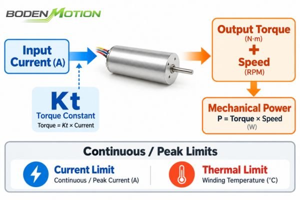
6. Continuous and Peak Torque
Continuous torque is the maximum torque the motor can produce continuously under specified ambient, mounting, and cooling conditions without overheating.3 Peak torque can only be sustained for a short time, limited by the driver's current limit and the motor's thermal capacity. Stall torque, the torque at zero speed, can cause rapid overheating unless the driver strictly limits the current and duration.
7. Mechanical Output Power
Output power is the product of torque and speed. It can be calculated using the relationship:
Mechanical Power (W) = Torque (N·m) × Speed (RPM) / 9.55
Rated output power must correspond to a defined operating point, not a multiplication of peak torque and no-load speed. For battery-powered or thermally constrained systems, the motor's efficiency at this operating point is a critical parameter for managing power consumption and heat.
8. Motor Constants (Kv and Kt)
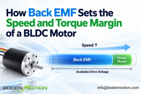
The torque constant (Kt) relates developed motor torque to current, while the speed constant (Kv, typically expressed in rpm/V) expresses rotational speed per volt. The back-EMF constant (Ke) describes induced voltage per unit of rotational speed.4 These constants are invaluable for matching a motor to a driver. Be cautious when comparing them between suppliers, as definitions (e.g., phase vs. line values for BLDC motors) can vary.
Why Thermal Limits Determine Whether Rated Performance Is Sustainable
All performance parameters—speed, torque, and power—are constrained by heat. If a motor cannot dissipate the heat generated by electrical and mechanical losses, its temperature will rise, potentially leading to winding failure or magnet demagnetization.
Continuous performance is defined by both electromagnetic capability and thermal equilibrium under specified cooling conditions. A datasheet that lists high peak torque without providing thermal resistance or continuous duty specifications is incomplete for many applications.
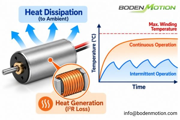
9. Thermal Ratings and Duty Cycle
Look for these key specifications:
- Maximum Winding Temperature: The highest temperature the motor windings can safely withstand.
- Thermal Resistance5: A measure of how effectively the motor dissipates heat. A lower value is generally better, but comparisons require equivalent measurement conditions. This is a crucial factor in determining the continuous torque limits in hollow cup motors.
- Application Duty Cycle6: This describes the load profile in your application (e.g., operating time vs. rest time), which is different from the PWM duty cycle of the driver. A motor's ability to handle an intermittent load depends on the peak current, duration, and rest interval, which allows it to cool.
How Dimensions and Mechanical Interfaces Affect Motor Integration
Once you have confirmed a motor can meet the performance requirements, the next step is to ensure it can be physically integrated into your device. This goes beyond simple length and diameter.
Mechanical compatibility is not just a dimensional fit; it also includes load paths, mounting precision, and bearing capabilities. An oversight here can lead to vibration, noise, or premature failure.

10. Motor Dimensions and Mechanical Interface
Check the complete mechanical drawing for:
- Total Installed Length: A motor with an encoder, gearbox, and connector can be much longer than the base motor body.
- Shaft Specifications: Diameter, length, and features like flats or pinions must match the driven component.
- Mounting Interface: The pattern and size of mounting holes must align with your assembly.
- Bearing Load: The datasheet may specify the maximum allowable radial (side) and axial (push/pull) loads on the shaft.7 Excessive shaft loading, including additional loads introduced by belt-driven mechanisms, can reduce bearing service life.8
How to Read Lifetime Ratings and Test Conditions Without Being Misled
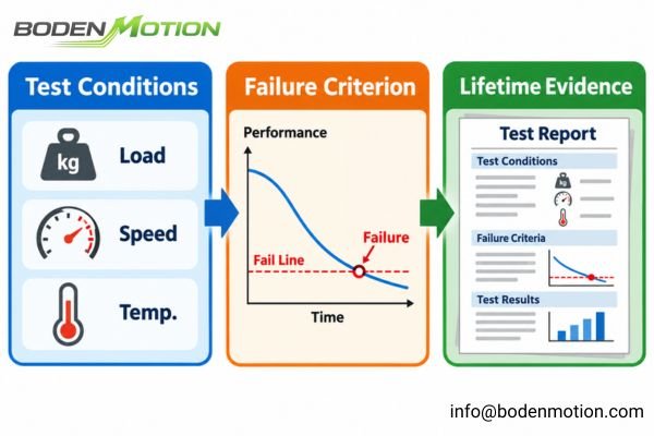
A lifetime rating on a datasheet can be one of the most misleading specifications if its context is ignored. A number without test conditions is not a reliable piece of evidence.
A lifetime number, speed value, or efficiency figure cannot be evaluated properly without knowing the conditions under which it was obtained. The "fine print" of the test conditions is often more important than the headline number itself.
11. Expected Lifetime
The datasheet might list a "typical lifetime," "design life," or "B10 life." It is crucial to understand what this means. Is it a guaranteed value, a statistical estimate based on testing, or simply a design target? These are not interchangeable. A statistically validated B10 lifetime is a much stronger piece of evidence than a vague "expected lifetime."
12. Test Conditions and Specification Tolerances
For any parameter on the datasheet, you must ask: how was this measured? The test conditions are the foundation for every other specification. Look for details on the supply voltage, load torque, ambient temperature, duty cycle, and the end-of-life criteria used for lifetime testing. Without this context, you cannot make a fair comparison between two different motors.
How OEM Engineers Should Compare Miniature Motor Datasheets
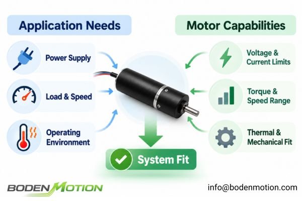
Evaluating a datasheet is not about finding the "best" motor in a vacuum; it is about finding the most suitable motor for a specific set of system constraints. This requires interpreting specifications as an interconnected system, not a list of independent figures.
A motor's specifications must be evaluated as a connected operating system. A change in one parameter, such as supply voltage or load, will affect others like speed, current, and thermal performance. The goal is to find a motor whose entire performance envelope matches the application's needs.
| No. | Parameter | Main Selection Question |
|---|---|---|
| 1 | Rated / Operating Voltage | Does it match the power supply? |
| 2 | No-Load Current | What does the baseline current indicate? |
| 3 | Rated / Peak Current | Can the driver and supply support it? |
| 4 | No-Load Speed | What is the unloaded speed reference? |
| 5 | Rated Speed | Can it reach the required speed under load? |
| 6 | Continuous / Peak Torque | Can it deliver torque for the required duration? |
| 7 | Mechanical Output Power | Is power sufficient at the actual operating point? |
| 8 | Motor Constants (Kv / Kt) | Do the winding characteristics match the drive? |
| 9 | Thermal Ratings / Duty Cycle9 | Can the motor operate without overheating? |
| 10 | Dimensions / Mechanical Interface | Does it fit and support the mechanical load? |
| 11 | Lifetime Rating | What reliability has actually been demonstrated? |
| 12 | Test Conditions / Tolerances | Are the specified values applicable and comparable? |
For an efficient evaluation, follow this sequence:
- Electrical Compatibility: Check voltage range and current requirements first.
- Required Operating Point: Verify the motor can deliver the necessary speed and torque simultaneously.
- Thermal Feasibility: Ensure the motor can sustain that performance without overheating under the required duty cycle.
- Mechanical Integration: Confirm the motor fits and that bearing loads are within limits.
- Reliability Evidence: Examine lifetime data and the underlying test conditions.
A practical example is comparing different windings of the same motor, such as the BDCM1725 coreless brushed DC motor. The 6V and 24V versions both have a nominal speed of 8,000 rpm, but their electrical characteristics are different:
- 6V version: 2.19 mN·m nominal torque at 0.41 A.
- 24V version: 2.72 mN·m nominal torque at 0.14 A.
These specifications refer to different winding configurations operating at their respective nominal voltages. The comparison shows that motors with the same physical dimensions and nominal speed can have different current and torque characteristics. The appropriate choice depends on the available supply voltage, required operating torque, and driver capabilities. A lower nominal current alone does not necessarily indicate lower power consumption or higher efficiency.10
Conclusion
A miniature motor datasheet should not be evaluated by isolated headline specifications such as maximum speed, peak torque, or rated voltage. Each value must be interpreted within its operating conditions and connected to a specific system requirement. Electrical compatibility, loaded performance, thermal limits, mechanical integration, and reliability evidence all influence whether a motor is suitable for an application.
For OEM engineers, the most useful approach is to read the datasheet in a defined decision sequence rather than treating every parameter as equally important. By identifying the required operating point, checking continuous performance, and verifying the underlying test conditions, engineers can compare different DC motor solutions more consistently and avoid selecting a motor that appears suitable on paper but fails to meet the needs of the complete system. Share your requirements with our team at info@bodenmotion.com to discuss your application requirements.
FAQ
Q1: What are the most important parameters in a miniature motor datasheet?
This depends on the application, but a core set includes operating voltage, current (rated and peak), speed and torque at the working point, thermal limits, key dimensions, and the conditions under which lifetime was tested.
Q2: What is the difference between no-load speed and rated speed?
No-load speed is the speed measured at a specified voltage without any external mechanical load. Rated speed is the motor's speed at a specific rated operating point, which includes a defined load torque and current.
Q3: Can I select a motor based on its peak torque value?
Not by itself. Peak torque is an intermittent rating. You must evaluate it alongside its allowable duration, the required current, and the motor's thermal limits to ensure it can be safely used in your application.
Q4: Why is rated current important when choosing a miniature motor?
Rated current informs the design of your power supply and driver. You must ensure your system can provide this current under the specified load conditions without faulting. Its definition can vary, so confirm if it refers to DC input or motor phase current.
Q5: Does higher motor output power always mean better performance?
No. High output power at an operating point you will never use is irrelevant. Performance should be judged by the motor's ability to efficiently and reliably meet your specific speed, torque, and duty cycle requirements.
Q6: Why do datasheets from different suppliers look so different?
Manufacturers use different parameter definitions, test conditions, motor architectures, and reporting formats. To compare them fairly, engineers should first identify differences in parameter definitions and test conditions, then request comparable measurements or application-specific data where necessary.
*Control Engineering*, "Slotless Versus Slotted Brushless DC Motors," explains slotted and slotless BLDC motor constructions and discusses their differences from coreless brushed motor technology. It supports these design distinctions, but is not a complete classification reference for every conventional brushed DC motor. ↩
"Lesson 8: DC Motors," Section 8.3, "Load of DC Motors," available on Scribd, describes no-load current as the current needed to keep an unloaded DC motor rotating against friction and windage. It provides a general explanation rather than miniature-motor-specific test data. ↩
"Motor Calculations," a FAULHABER-authored technical tutorial hosted by Michigan Technological University, especially "Thermal Calculations," explains how winding resistance, allowable temperature rise, ambient temperature, thermal resistance, and heat dissipation affect permissible continuous current and torque in a coreless brushed DC motor. Mounting and cooling conditions can alter the resulting limits. ↩
FAULHABER, "Brushless DC-Motors — Technical Information," p. 4, separately defines the speed constant (kn, in min^-1/V), back-EMF constant (kE, in mV/min^-1), and torque constant (kM, in mNm/A). The manufacturer uses kn and kM for quantities commonly called Kv and Kt in other motor literature. The notation and units must be checked when comparing datasheets. ↩
Wikipedia, "Thermal Conductance and Resistance," defines thermal resistance as the temperature difference across a thermal path divided by the heat-transfer rate, commonly expressed in K/W. Lower thermal resistance produces a smaller steady-state temperature rise at the same dissipated power and equivalent boundary conditions; the article is not motor-specific. ↩
Wikipedia, "Duty Cycle," defines duty cycle as the active fraction of a repeating period and describes thermal limitations of intermittent motor operation. A motor application's run/rest schedule and a driver's PWM switching duty cycle share a mathematical definition but refer to different operating phenomena. ↩
Oriental Motor, "Motor Sizing Basics Part 4: How to Calculate Radial Load and Axial Load," defines permissible radial and axial loads and illustrates how manufacturers provide them in motor and gearhead specifications. The discussion primarily concerns industrial motor and gearhead arrangements rather than miniature coreless motors. ↩
SKF, "Bearing Damage and Failure Analysis," June 2025, pp. 6 and 20, explains that increasing external bearing loads reduces bearing service life. It identifies a change from coupling to belt drive as a situation that requires reassessing bearing loads. The document discusses rolling bearings generally rather than specific miniature motor bearing ratings. ↩
Michael Greig, "What Is Duty Cycle?," Actuonix Motion Devices (2025), explains how motor-driven linear actuators' permitted run and rest periods depend on heat generation, load, ambient temperature, supply conditions, and cooling. The guidance is primarily about integrated actuators rather than all thermal rating parameters of standalone motors. ↩
U.S. Department of Energy, "Determining Electric Motor Load and Efficiency," Motor Challenge Fact Sheet, DOE/GO-10097-517 (1997), pp. 3, 5, and 7, explains that input power is not determined by current alone and that efficiency compares useful mechanical output power with electrical input power. Its calculations primarily address industrial three-phase AC motors; the three-phase power-factor formula should not be directly applied to miniature DC motors. ↩