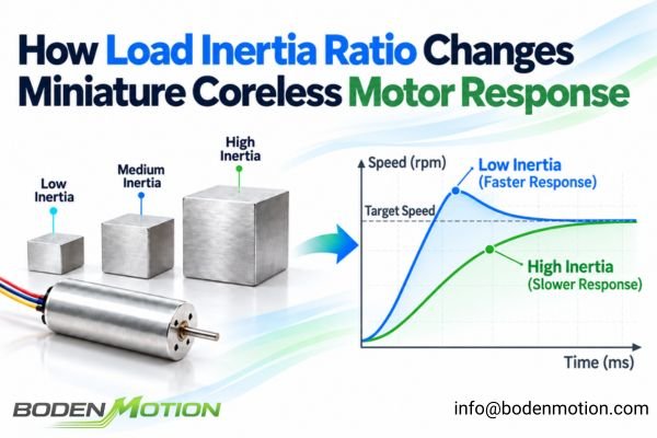
Miniature coreless motors are often selected for their low rotor inertia and rapid acceleration. However, this impressive no-load performance doesn't always translate directly to the final application, as the system's actual dynamic response is determined by the motor and the load working together.
A coreless motor's low rotor inertia is only half of the equation; the load inertia reflected back to the motor shaft contributes to the total equivalent rotational inertia, directly impacting the system's acceleration, control response, and positioning time.
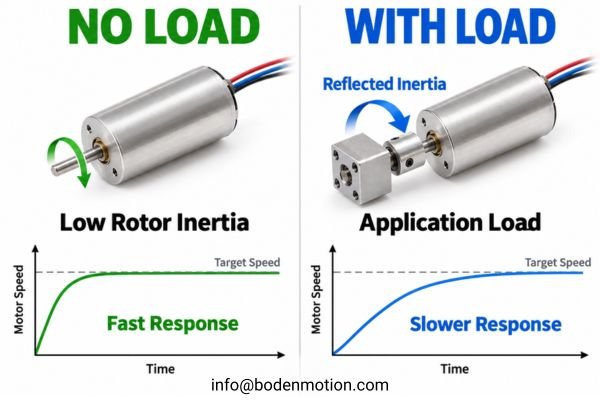
A coreless motor that accelerates rapidly during no-load testing may respond much more slowly when connected to a gearbox, robotic joint, or lead screw. The actual response depends on the total equivalent inertia, transmission ratio, and available acceleration torque. For OEM engineers, the key is determining whether the motor can meet the required motion cycle under real load conditions. Explore BODENMOTION's coreless motors to evaluate suitable motor configurations.
What Is Load Inertia Ratio in a Coreless Motor System?
Before diving into control tuning, we need to understand the fundamental mechanical relationship. The load inertia ratio compares the external load inertia, as seen by the motor shaft, to the motor's own rotor inertia.
The inertia ratio is a dimensionless number that indicates the load's relative influence on the system's dynamics. A higher ratio means the load's inertia is larger relative to the motor's own inertia, although the ratio alone does not determine the system's acceleration or stability.
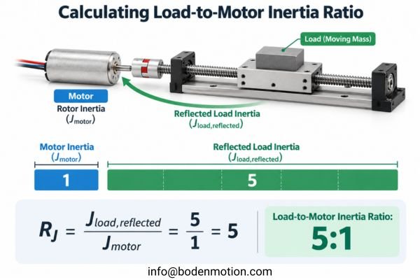
This relationship is expressed as:
R_J = J_load,reflected / J_motor
Where:
R_Jis the load-to-motor inertia ratio.J_load,reflectedis the load inertia reflected to the motor shaft.J_motoris the motor's rotor inertia, found on the datasheet.
For example, an inertia ratio of 5:1 means the reflected load inertia is five times greater than the motor's rotor inertia. It's a common misconception that a specific ratio like 1:1 is always ideal or that any ratio above 10:1 is automatically unstable. The acceptable range is highly dependent on the driver's capability, the control algorithm, the mechanical stiffness of the system, and the specific motion requirements1.
Why Low Rotor Inertia Does Not Always Produce Fast Acceleration
The core of motion dynamics lies in Newton's second law for rotation. The angular acceleration of a system is directly proportional to the available torque and inversely proportional to the total inertia.
A motor's fast response comes from its torque-to-inertia capability. While coreless motors can offer favorable rotor torque-to-inertia characteristics, they cannot eliminate the inertia of the external load they are tasked with moving.
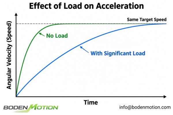
The governing equation is:
T_acc = J_total × α
Where:
T_accis the net torque available for acceleration (motor torque minus friction and external load torque).J_totalis the total equivalent inertia at the motor shaft. In a simplified model, it equalsJ_motor + J_load,reflected. Practical geared systems must also account for the equivalent inertia of the gearbox and other moving components.αis the resulting angular acceleration.
When the total inertia (J_total) increases due to a heavier reflected load, the same available acceleration torque (T_acc) will produce a lower angular acceleration (α). This highlights why looking at the ratio alone is insufficient; engineers must also consider the motor's absolute torque capacity to accelerate the total inertia.
How the Same Coreless Motor Behaves With Two Different Loads
To make this practical, let's consider a simplified numerical example with a single coreless motor used in two different applications. Assume the motor has the same available net acceleration torque in both cases.
The motor has not changed; the load has changed the system's response. A heavier reflected load demands significantly more torque for the same rate of acceleration or results in slower acceleration for the same available torque.
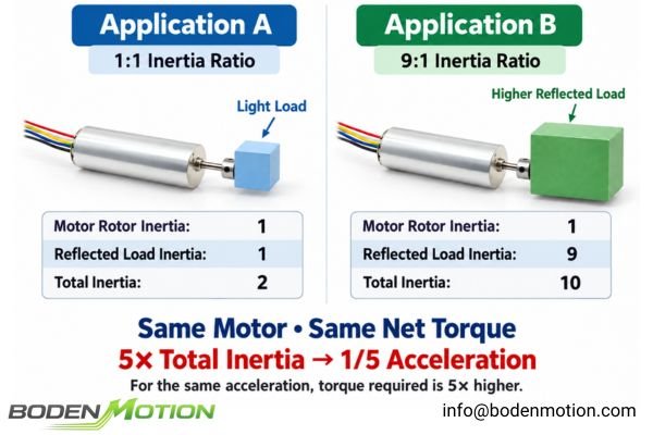
Let's use normalized units for this illustrative example:
| Parameter | Application A (Light Load) | Application B (Heavy Load) |
|---|---|---|
| Motor Rotor Inertia | 1 unit | 1 unit |
| Reflected Load Inertia | 1 unit | 9 units |
| Inertia Ratio | 1:1 | 9:1 |
Total Inertia (J_total) |
2 units | 10 units |
Resulting Acceleration (α) |
High (Reference) | Reduced to 1/5 |
| Torque for Same Acceleration | Low (Reference) | 5× Higher |
This is a simplified, normalized example for educational purposes and does not represent specific product data. It assumes the net acceleration torque is constant.
This comparison makes it clear that in Application B, the system's total inertia is five times higher than in Application A. Consequently, with the same net torque, the angular acceleration is reduced to one-fifth of its original value. This physical relationship helps explain why a motor that responds quickly on its own can feel sluggish once integrated into a mechanism with a significant load.
How Gear Ratio Changes the Load Inertia Seen by the Motor
In many OEM devices, the load is not directly coupled to the motor. A transmission mechanism like a gearbox or belt drive is used to trade speed for torque, which has a profound effect on the load inertia reflected back to the motor.
A reduction gearbox is a powerful tool for improving inertia matching. It reduces the load inertia seen by the motor by the square of the gear ratio, but this benefit must be weighed against trade-offs such as motor operating speed, transmission losses, backlash, and mechanical stiffness.
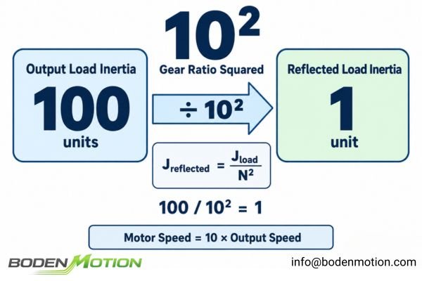
For an ideal transmission, the inertia of the output load is reflected back to the motor shaft according to this formula:
Where N is the gear ratio (ω_motor / ω_output).
For example, if an output load has an inertia of 100 units and is driven by a 10:1 gearbox (N = 10), the inertia reflected back to the motor is:
J_reflected = 100 / 10² = 1 unit
However, a complete engineering analysis must also consider that a higher gear ratio requires the motor to run at a higher speed to achieve the same output speed.
In practical geared systems, the total equivalent inertia must also include the gearbox's own rotating inertia and other mechanically coupled components3. Each component's inertia should be referred to the motor shaft according to its rotational speed relative to the motor. Ignoring these contributions can lead to an inaccurate estimate of the torque required for acceleration, particularly in compact mechanisms where transmission inertia is significant.
The motor's available torque at the required operating speed, along with the gearbox's efficiency, backlash, and torsional stiffness, also influences the final system dynamics. Reducing reflected load inertia does not automatically guarantee a shorter output motion cycle.
How Inertia Ratio Affects Control Loop Response and Settling Time
In closed-loop speed or position control systems, the interaction between motor inertia, reflected load inertia, and mechanical compliance influences controller tuning and dynamic response. The inertia ratio provides useful information about the mechanical system, but it does not independently determine control bandwidth, stability, or settling time.
A high inertia ratio does not automatically cause overshoot, but it can make the system more challenging to control. The system's response depends on the entire closed loop, including controller gains, mechanical compliance, available torque, and feedback characteristics.
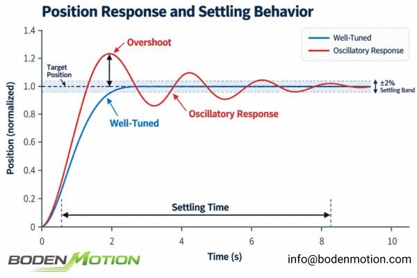
For the same available torque, a higher total inertia reduces the achievable acceleration. While it might seem intuitive to increase controller gains to compensate, this can be counterproductive.
If the mechanical transmission between the motor and load is not perfectly stiff—if there is compliance in the shaft, coupling, or gearbox—aggressive gains can excite mechanical resonances, leading to4:
- Overshoot: The load moves past its target position.
- Oscillation: The system "hunts" around the target position.
- Long Settling Time: The time required for the load to enter and remain within a specified tolerance band around the target increases.
Therefore, controller parameters must be tuned based on the complete system's characteristics, not just the inertia ratio. A system with a high inertia ratio and a flexible coupling may require lower control gains or other control adjustments to maintain stability, potentially at the cost of slower response.5
Why Repeated Acceleration and Reversal Increase Thermal Demand
In robotics and automation, motors execute rapid, repetitive motion cycles. Accelerating and decelerating a large total inertia requires substantial torque, which can increase electrical and thermal demands during repeated operation.
A motor may satisfy the peak torque requirement for a single move but exceed its thermal limits during continuous operation. Repeated acceleration of a large inertia can increase RMS current, depending on the motion profile and duty cycle, resulting in additional heat from motor copper losses.
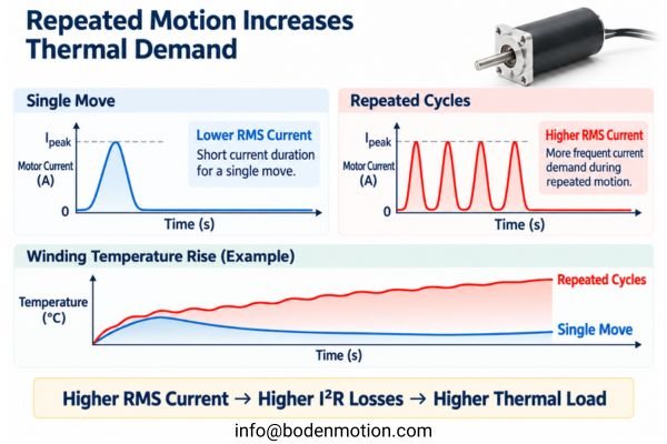
To maintain a fast motion cycle with a large total inertia, the motor must produce sufficient acceleration torque. This can require high peak current from the driver.
There are two major considerations:
- Driver Sizing: The motor driver must be capable of supplying the required peak current without exceeding its operating limits.
- Thermal Load: The current waveform over the complete duty cycle determines the RMS (root mean square) current. Higher RMS current increases heat generation in the motor windings through
I²Rlosses.
During deceleration, the system's rotational kinetic energy must be removed from the moving mechanism, either through energy recovery or dissipation.
The rotational kinetic energy is given by6:
E_k = ½ × J_total × ω²
Depending on the drive architecture, this energy may be returned to the DC bus or power supply through regenerative braking, dissipated in a braking resistor, or converted into mechanical and electrical losses elsewhere in the system.
Therefore, the thermal impact of repetitive operation cannot be determined from inertia ratio alone. Engineers must evaluate the complete current profile, motor winding resistance, duty cycle, thermal conditions, and the driver's energy-handling capabilities.
Why a Lower Inertia Ratio Does Not Always Mean Better Motor Performance
Engineers often seek the lowest possible inertia ratio, but this can be a misleading metric when comparing different motor solutions. The best motor choice depends on the total system inertia, the motor's available torque, and the actual motion requirements.
The inertia ratio is a relative measure, while acceleration is governed by the absolute total inertia and the available net torque. A motor with a higher inertia ratio can still outperform one with a lower ratio if its lower rotor inertia results in a smaller total system inertia under otherwise comparable conditions.
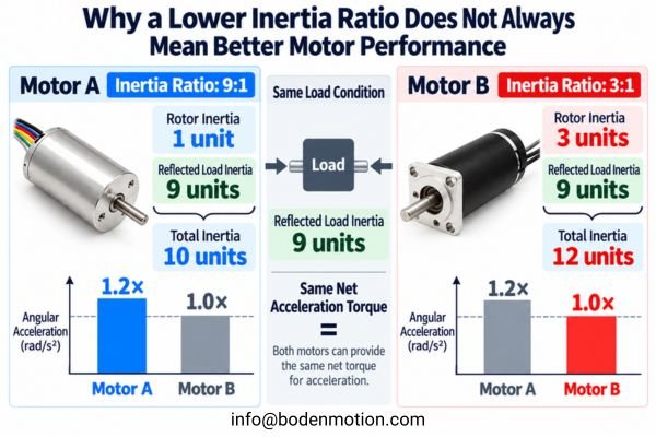
To illustrate, consider selecting between two different motors for the same reflected load inertia of 9 units.
| Parameter | Motor A | Motor B |
|---|---|---|
| Rotor Inertia | 1 unit | 3 units |
| Reflected Load Inertia | 9 units | 9 units |
| Inertia Ratio | 9:1 | 3:1 |
| Total Inertia | 10 units | 12 units |
This is a simplified, illustrative example using normalized inertia values. It assumes both motors drive the same reflected load and can provide the same net acceleration torque.
In this case, Motor B has a lower inertia ratio of 3:1. However, Motor A, despite its higher 9:1 ratio, results in a lower total system inertia (10 units vs. 12 units).
If both motors can provide the same net acceleration torque, Motor A will produce 20% higher angular acceleration7 because it is accelerating a smaller total inertia.
This demonstrates why selecting a motor based solely on the inertia ratio can produce misleading conclusions.
In practice, OEM engineers must compare several factors together:
- Total Equivalent Inertia: Determines how much inertia the motor must accelerate.
- Available Motor Torque: Determines the achievable acceleration at the required operating speed.
- Motion Profile: Defines the necessary acceleration, speed, travel distance, and positioning time.
- Mechanical and Control Limits: Influence the achievable bandwidth, stability, and settling time.
- Electrical and Thermal Limits: Determine whether the required motion can be repeated without exceeding safe operating conditions.
The optimal motor is not necessarily the one with the lowest inertia ratio or absolute inertia. It is the motor that can meet the required motion profile while operating within its mechanical, electrical, control, and thermal limits.
How OEM Engineers Should Evaluate Coreless Motor Inertia Matching
A structured approach is the best way to ensure a motion system will perform as expected. This involves analyzing the complete mechanism, from motion requirements and load inertia to motor torque, control response, and thermal limits.
A successful integration starts with a detailed motion profile and a complete inventory of all moving components. Validate the entire electromechanical system under realistic operating conditions, rather than relying only on a no-load motor test or a single inertia ratio.
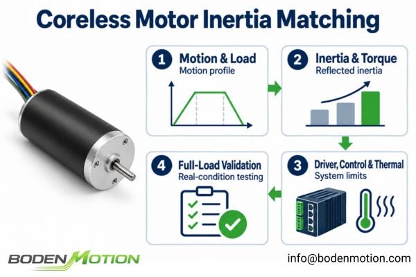
Follow these steps for a robust evaluation:
- Define the Motion Profile: Specify target speed, acceleration/deceleration times, travel distance, and cycle frequency.
- Determine All Inertias: Obtain rotor inertia from the motor datasheet. Calculate the inertia of the load, gears, couplings, and other moving parts.
- Calculate Reflected Inertia and Ratio: Use the transmission ratio to reflect all external inertias back to the motor shaft and determine the total equivalent inertia and inertia ratio.
- Calculate Required Torque: Determine the peak torque required for acceleration, considering total inertia, friction, and external forces.
- Check Motor & Driver Limits: Ensure required peak torque, operating speed, peak current, and RMS current are within the motor and driver's specified operating limits.
- Assess Mechanical and Control Response: Consider mechanical stiffness, potential resonance, feedback characteristics, and the control bandwidth needed to achieve the required settling time and positioning accuracy.
- Validate Performance: Test the complete system under full load and during continuous, repetitive cycling to verify positioning performance, current demand, and thermal behavior.
This process is particularly important when evaluating miniature coreless motors for compact actuators, robotic mechanisms, precision positioning systems, and other applications with demanding motion cycles8.
Instead of focusing only on motor speed or inertia ratio, OEM engineers should provide the actual load characteristics, transmission details, operating conditions, and required motion profile.
These parameters allow motor performance to be evaluated against the real application9 rather than a theoretical no-load condition.
Conclusion
Miniature coreless motors offer strong dynamic potential, but this potential is only realized when the motor is properly matched to the load. The total equivalent inertia—the sum of the motor's rotor inertia and the reflected load inertia, together with other relevant drivetrain inertias—determines the torque required for a given acceleration and influences the system's dynamic response. Higher reflected load inertia increases torque demand for the same acceleration, while a high load-to-motor inertia ratio may introduce additional control challenges depending on mechanical stiffness and controller capabilities.
For OEM engineers, the best motor is not necessarily the one with the lowest rotor inertia or inertia ratio, but the one that provides the appropriate balance of torque, speed, controllability, and thermal capability for the actual motion profile. A deeper understanding of these relationships is useful when specifying coreless motors for low-inertia applications. For assistance evaluating inertia matching in your next precision motion project, contact our engineering team at info@bodenmotion.com with your motion profile and mechanism details.
FAQ
Q1: What is the load inertia ratio for a coreless motor?
It is the ratio of the external load inertia, as reflected to the motor shaft, divided by the motor's own rotor inertia. It indicates the relative contribution of the load inertia to the system's total equivalent inertia.
Q2: Does a higher inertia ratio always cause slower acceleration?
For the same motor and available net acceleration torque, increasing the reflected load inertia increases the total inertia and reduces angular acceleration according to α = T_acc / J_total. However, when comparing different motors, a higher inertia ratio does not necessarily mean slower acceleration because total inertia and available torque may differ.
Q3: Is there an ideal load-to-motor inertia ratio?
There is no universal ideal ratio. Lower ratios can simplify control in some motion systems, but the acceptable ratio depends on mechanical stiffness, driver capabilities, control strategy, and motion requirements. A higher ratio does not automatically make a system unstable.
Q4: Can a gearbox improve inertia matching?
Yes. An ideal reduction gearbox decreases the load inertia reflected to the motor shaft by the square of the reduction ratio. However, its own inertia, efficiency, backlash, and the motor speed required to achieve the target output motion must also be considered.
Q5: Does a high inertia ratio always cause overshoot?
No. Overshoot is a closed-loop system phenomenon influenced by controller gains, mechanical compliance, damping, feedback characteristics, and available torque. A high inertia ratio may make control more challenging in some systems, but it does not automatically cause overshoot.
Q6: What information is needed for an inertia matching analysis?
To perform a thorough analysis, provide the motor's rotor inertia, the inertia of all moving load components, the transmission ratio, and the complete motion profile. This should include target speed, acceleration time, travel distance, cycle frequency, and any requirements for positioning accuracy and settling time.
Mitsubishi Electric's “Understanding Inertia Ratio and Its Effect On Machine Performance” explains why an acceptable load-to-motor inertia ratio depends on the application's settling-time and positioning requirements, mechanical stiffness, and the servo drive's control and filtering capabilities rather than a universal rule of thumb. ↩
D. Z. Chen and L. W. Tsai's “The Generalized Principle of Inertia Match for Geared Robotic Mechanisms” examines inertia matching in geared mechanisms and the relationship between transmission ratio and equivalent inertia. The inverse-square reflected-load formula follows when the gear ratio is defined as motor speed divided by output speed. ↩
Erik Cheever's “Gears and Systems with both Rotation and Translation,” from Swarthmore College, derives the equations of motion for coupled gears and shows that the inertias of multiple rotating elements contribute to the equivalent inertia through the squared gear-radius ratio. ↩
George Ellis's “Cures for Mechanical Resonance in Industrial Servo Systems,” published by Kollmorgen, explains how high servo gains can destabilize a mechanically compliant motor-load system. Laboratory tests illustrate oscillation, overshoot, settling-time limitations, and improvements from suitable filtering and feedback control. ↩
George Ellis's “How to Work with Mechanical Resonance in Motion Control Systems,” published in Control Engineering, discusses how load-to-motor inertia ratio, mechanical compliance, and controller gains affect servo stability, including the trade-offs involved in gain reduction and resonance filtering. ↩
Michigan State University's “Rotational Kinetic Energy: Work and Energy Revisited” derives the rotational kinetic energy relationship, showing that stored energy depends on rotational inertia and the square of angular velocity. ↩
The “Dynamics of Rotational Motion: Rotational Inertia” chapter in College Physics explains that, for a given net torque, angular acceleration is inversely proportional to moment of inertia. The 20% difference in the article is calculated from its illustrative total inertias of 10 and 12 units, not from a published motor test. ↩
MOONS' “Technical Advantages of Coreless Motors” discusses the low-inertia, fast-response characteristics of coreless motors relevant to compact motion applications, including mechanisms that require frequent acceleration and deceleration. ↩
Oriental Motor's “Motor Sizing Calculations” explains how motor selection should account for application-specific load inertia, load and acceleration torque, operating speed, motion profile, and duty-cycle requirements. ↩