In precision motion systems such as surgical tools, micro-robotics, and compact actuators, the real engineering limitation is often not torque or speed, but inertia management under control feedback. Once inertia becomes too high, the system response is delayed, overshoots become harder to suppress, and tuning margins shrink significantly.
Coreless motors are frequently introduced in these applications because they fundamentally reduce rotor inertia. However, from an OEM engineering perspective, the value is not “faster motor response” in isolation. The real value is how low inertia reshapes the entire control system behavior, including stability margin, tuning sensitivity, and mechanical coupling requirements.
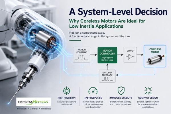
In practice, selecting a coreless motor is less about performance upgrade and more about system architecture change.
Why does inertia dominate performance in precision motion systems?
In low-scale precision systems, inertia is not just a mechanical parameter—it defines how the system reacts to control input.
A high-inertia motor tends to smooth out motion naturally, but that same “stability” becomes a limitation when rapid direction change or micro-positioning is required. Coreless motors reduce this mechanical lag, which allows control loops to operate closer to theoretical response limits.
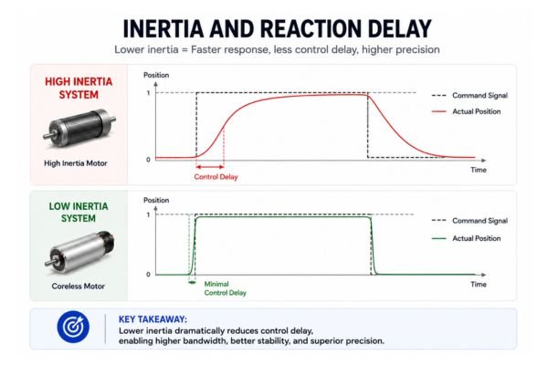
From an engineering standpoint, the key difference is not speed itself, but delay between input command and mechanical reaction. In high-precision applications, even small delays accumulate into control instability.
In many OEM designs, this is where performance bottlenecks are first observed—not in steady-state operation, but in transition behavior.
What makes coreless motor structure fundamentally different?
The structural distinction is simple but impactful: removing the iron core from the rotor changes both mass distribution and electromagnetic behavior.
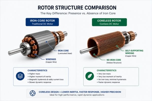
Without an iron core:
- Rotor mass is significantly reduced
- Moment of inertia drops sharply
- Magnetic hysteresis effects are minimized
- Commutation response becomes more linear
This is not just a weight reduction effect. The more important change is that electromagnetic response becomes more directly coupled to input current changes, reducing internal delay.
In system terms, this means the motor behaves more like an “instant response actuator” rather than a stored-energy mechanical system.
How does low inertia affect closed-loop control behavior?
When inertia is reduced, control systems behave differently—sometimes in ways engineers do not expect during initial integration.
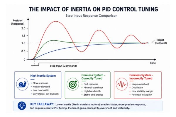
In closed-loop systems, the controller assumes a certain mechanical response delay. When that delay is significantly reduced, the system can become:
- More responsive
- More sensitive to parameter tuning
- More prone to oscillation if not retuned
A simplified relationship is often observed in practice:
From OEM tuning experience, a frequent adjustment requirement is reducing aggressive PID gains that were originally tuned for higher inertia systems. Without this adjustment, the system may exhibit micro-oscillation even if the mechanical design is correct.
What integration challenges appear in real OEM systems?
Coreless motors introduce advantages, but they also expose weaknesses elsewhere in the system.
One of the most common integration challenges is mechanical rigidity sensitivity. Because the motor reacts faster, any mechanical backlash or compliance becomes more visible in output motion. In systems with flexible coupling or long transmission paths, this can reduce perceived precision instead of improving it.
Another practical issue is thermal behavior under dynamic operation. Although coreless motors have lower inertia, they are often used in high-frequency motion systems where acceleration and deceleration cycles are continuous. This creates non-uniform thermal loading, which is different from steady-state motor heating.
Electrical noise sensitivity is another factor. Faster response means current changes occur more abruptly, which can expose limitations in driver design or power supply stability.
What trade-offs must engineers consider during selection?
Coreless motors are not universally superior—they are optimized for a specific operating regime. In OEM design, trade-offs must be explicitly evaluated.
| Design Factor | Coreless Motor Behavior | Engineering Implication |
|---|---|---|
| Inertia | Very low | High responsiveness |
| Torque density | Moderate | May require sizing adjustment |
| Thermal behavior | Cycle-dependent | Needs duty cycle validation |
| Mechanical robustness | Lower than iron-core | Requires careful protection |
| Control sensitivity | High | Requires tuning refinement |
The most important design decision is not whether coreless is better, but whether the system actually requires low inertia dynamics.
How should coreless motors be tested in OEM development?
Testing methodology is often where selection success or failure is determined.
A common mistake is evaluating coreless motors only under steady-state load. This does not reflect real behavior in precision applications.
More meaningful test conditions include:
- Rapid acceleration and deceleration cycles
- Repeated short-stroke positioning tests
- Back-and-forth directional switching
- Load variation under continuous motion
- Controller stability under parameter variation
In many OEM validation cycles, issues only appear during transition testing, not steady-state operation. This is why dynamic testing is more representative than static torque measurement.
Another important observation from engineering practice: performance degradation often appears first as control instability, not mechanical failure.
When does low inertia become a disadvantage?
Low inertia is not always beneficial. In some systems, it can introduce unnecessary complexity.
For example:
- Systems requiring smooth, damped motion may become harder to control
- High load inertia mismatch can cause instability
- Cost-sensitive applications may not justify tuning effort
- Mechanical shock environments may reduce reliability advantages
In these cases, traditional iron-core motors provide more predictable behavior with less tuning effort.
A practical engineering principle applies here: if inertia is not a limiting factor, reducing it may not improve system performance.
How should engineers evaluate system-level fit?
Motor selection should never be isolated from system architecture. In low inertia applications, the most important evaluation factors are not just motor parameters, but interaction behavior.
Key system-level questions include:
- Does the control loop bandwidth match motor response speed?
- Is mechanical structure rigid enough to utilize fast response?
- Is load inertia compatible with rotor inertia ratio?
- Can the system tolerate higher control sensitivity?
- Is thermal cycling behavior acceptable for duty profile?
These questions often determine success more accurately than datasheet comparison.
Conclusion
Coreless motors are ideal for low inertia applications because they fundamentally change system responsiveness, not just motor performance. Their value appears only when the entire system—mechanical, electrical, and control—is designed to take advantage of fast dynamic behavior.
In OEM engineering practice, the real challenge is not choosing a faster motor, but ensuring the system can remain stable under increased responsiveness.
For application-level evaluation and OEM integration support, BODENMOTION provides engineering assistance for system-optimized motor selection.
Contact: info@bodenmotion.com