Your new device requires precise, stable motion, but the miniature brushless DC motor you've selected is either unstable at low speeds or generates too much noise.
For many miniature brushless DC motor applications, PWM speed control becomes important when the system requires adjustable speed, controlled startup, low-speed stability, or better thermal management. While not every fixed-speed application needs it, PWM provides a critical control interface for more demanding OEM systems.
In a compact OEM device, a motor isn't just expected to spin at full speed. It needs to integrate seamlessly into a larger system, responding to control inputs, adapting to changing loads, and operating quietly. Because miniature BLDC motors have such a fast response time, their speed can change dramatically with any fluctuation in load or power. This is where PWM control becomes a key part of achieving real-world system performance1.
What PWM Speed Control Means in a Miniature Brushless DC Motor
Many engineers see PWM as just a way to adjust speed, but its role in a miniature motor system is more about providing a controllable interface.
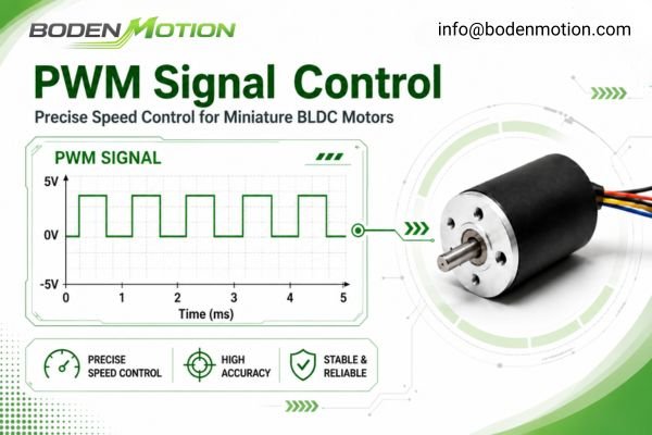
PWM, or Pulse Width Modulation, is a technique that adjusts the "duty cycle" (the on-time percentage) of a rapidly switching signal to control the average power delivered to the motor. In practice, however, PWM does not work alone. The final motor behavior depends on how the driver interprets the PWM signal, how it commutates the motor, and whether its logic includes current limiting, soft-start, or speed feedback.
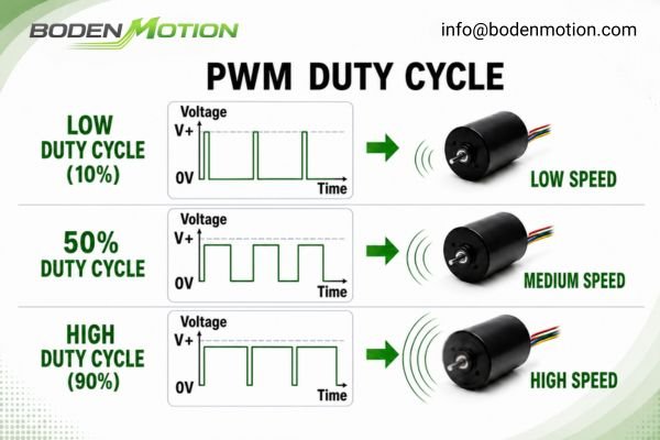
For a miniature brushless motor, the PWM signal and the driver logic together dictate the motor's dynamic behavior within the application.
This system-level control influences:
- Startup Profile: Determines if the motor starts smoothly or aggressively.
- Acceleration and Deceleration: Controls the speed ramp-up and ramp-down rates.
- Speed Range: Defines the achievable minimum and maximum stable speeds.
- Low-Speed Stability2: Affects smoothness and reduces cogging or jerking at low RPM.
- Load Response: Manages how the motor compensates for changes in load.
- Acoustic Noise: The PWM frequency itself can be a source of audible noise3.
- Thermal Output: Allows speed reduction to manage heat under light loads.
Why Low Rotor Inertia Makes Speed Control More Sensitive
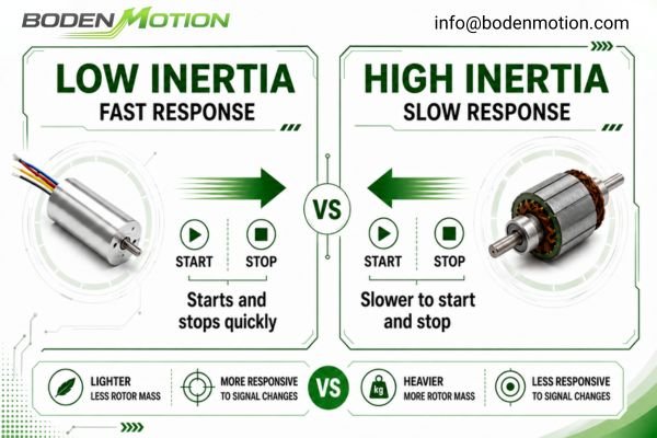
A miniature brushless motor's low rotor inertia is excellent for fast acceleration, but it also reduces natural mechanical damping, making the system more sensitive to control inputs and load variations.
A larger motor with a heavy rotor has enough inertia to smooth over minor fluctuations in the drive signal or load. A miniature motor does not have this luxury; its speed will try to follow every ripple and jitter in the control system. This is often a system integration issue, not simply a motor quality issue.
This high sensitivity can manifest as:
- Speed Fluctuation: The motor's RPM is not stable, even under a seemingly constant load.
- Low-Speed Instability: The motor may jerk or stall at very low speeds.
- Startup Vibration: The motor oscillates or "buzzes" before it starts rotating smoothly.
- Audible Noise Changes: The motor's sound changes pitch and volume with small load variations.
System-Level Observation: For many small motion systems, achieving precise speed control is more critical than simply specifying a motor with a high no-load speed. A motor that can hold a stable speed under a variable load is often more valuable than one that is unstable4
How PWM Improves Startup Stability
In many miniature motor applications, the initial startup phase is the most challenging part of the motion profile. An uncontrolled startup can send a shockwave through the system.
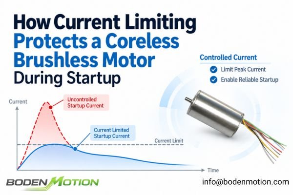
PWM control allows the driver to implement a "soft-start" strategy, managing the process gradually. Instead of applying full power instantly, the driver can ramp the PWM duty cycle from 0% to the target level over a defined period (for example, 100–500 ms, depending on load inertia).
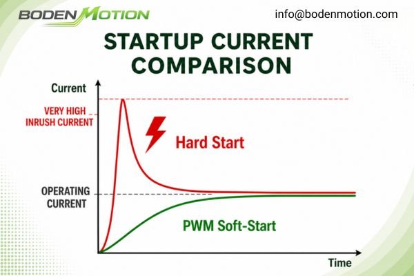
Imagine turning on a small centrifugal pump. If the motor starts instantly, the inrush current can be massive, potentially tripping the power supply. Mechanically, this "kick" can cause vibration or even damage. A controlled soft start avoids this.
Benefits of a PWM-controlled soft start include:
- Lower Inrush Current5: Prevents power supply brownouts or over-current protection trips.
- Reduced Mechanical Shock6: Protects gearboxes, couplings, and the attached load from impact stress.
- Quieter Operation: Eliminates startup "thumps" or "clicks."
- Improved Startup Under Load: Helps the motor overcome static friction and inertia without stalling.
In my experience with medical devices and laboratory instruments, a smooth and repeatable startup is often a non-negotiable requirement. This should be validated with the real load.
Why PWM Frequency Affects Noise and Low-Speed Operation
The PWM frequency you choose is not just an electrical setting; it's a parameter that directly affects how your device sounds and how smoothly it operates.
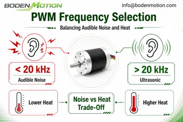
If the PWM frequency falls within the range of human hearing, roughly 20 Hz to 20 kHz, the motor's magnetic components may vibrate at that frequency and create an audible whine. For this reason, many noise-sensitive applications evaluate PWM frequencies above 20 kHz, moving the switching noise into the ultrasonic range.
However, frequency selection involves important engineering trade-offs.
| PWM Frequency | Potential Pros | Potential Cons |
|---|---|---|
| Low, below 15 kHz | Lower switching losses; lower driver heat in some designs. | May be audible; may increase torque ripple and low-speed vibration. |
| High, above 20 kHz | Quieter operation; smoother torque delivery; better low-speed stability in some systems. | Higher switching losses; increased driver temperature; higher driver component requirements. |
Design Trade-Off:
There is often a tension between acoustic performance and thermal management. A higher PWM frequency may solve a noise problem, but it can also cause the motor driver to run hotter.7 This is why the motor and driver should be tested together in a setup that simulates the final product's thermal environment. The final frequency should be confirmed based on driver specifications, acoustic requirements, load conditions, and measured temperature rise.
How PWM Supports Thermal Management in Compact Systems
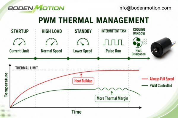
In a compact, sealed device, every milliwatt of wasted energy turns into heat. When the load profile allows speed reduction, PWM control can reduce average power consumption and help limit heat generation.
Running a miniature motor at full speed when it's not necessary is a major source of excess heat. The actual thermal benefit of using PWM depends on the load type, driver efficiency, duty cycle, airflow, and enclosure design. It allows the system to match motor output to real-time demand.
PWM control enables several heat-reduction strategies:
- On-Demand Performance: Running the motor at a lower speed during standby or low-load phases.
- Current Limiting: Using the driver to actively limit current during startup and high-load events.
- Duty Cycle Management: For intermittent tasks, the motor can run for a short period and then be slowed, allowing time for heat to dissipate.
Real Integration Challenge: From my experience, many compact systems start to have problems when the heat from the motor affects a nearby sensor, deforms a plastic part, or makes the device housing uncomfortably warm. Effective PWM control is a form of proactive thermal management.
What OEM Buyers Should Confirm Before Selecting a PWM-Controlled BLDC Motor
When your project requires adjustable speed, you are selecting a motor system, not just a standalone motor. The PWM signal, driver logic, load condition, power supply, and feedback method all affect the final performance.
Before confirming a sample, it is useful to discuss the control interface and application conditions with your supplier. Clear information at this stage helps reduce integration problems later.
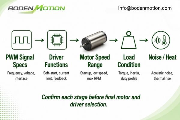
The following points are usually worth confirming during the sample evaluation stage:
| Confirmation Item | What to Check |
|---|---|
| Voltage and Speed Range | Supply voltage, target RPM range, and required minimum stable speed. |
| Load and Startup Condition | Load type, startup torque, friction, and whether the motor starts under load. |
| PWM Input Signal | PWM voltage level, such as 3.3V or 5V, and recommended frequency range. |
| Duty Cycle Behavior | Effective duty cycle range and what happens at 0% or 100% duty cycle. |
| Driver Functions | Soft-start, current limiting, CW/CCW control, braking, and protection logic. |
| Feedback Requirement | Whether FG speed feedback is needed for monitoring or closed-loop control. |
| Noise and Thermal Limits | Acoustic limits, driver temperature, motor housing temperature, and enclosure condition. |
| Connection and Integration | Wire length, connector type, PCB interface, and reference wiring diagram. |
This information allows the supplier to evaluate whether the motor and driver combination is suitable for your application. It also helps identify whether a standard driver is enough or whether a customized control interface should be discussed.
Common PWM Control Mistakes in Miniature BLDC Motor Applications
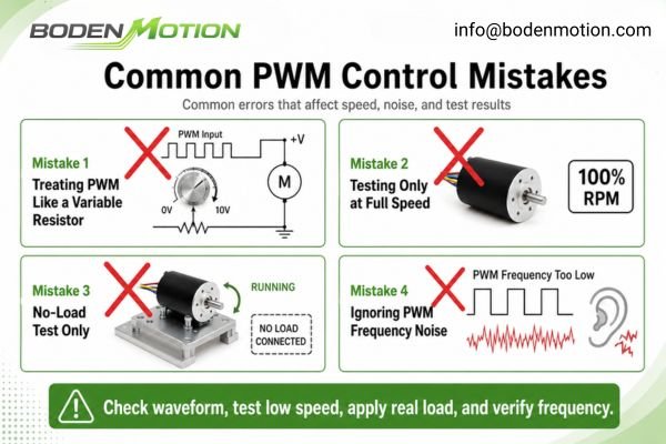
I've seen many OEM teams struggle with PWM integration. Usually, the problems stem from a few common misunderstandings about how these motor systems work.
These mistakes can lead to project delays and performance issues that are hard to diagnose late in the development cycle.
-
Common OEM Mistake: Treating PWM as Simple Voltage Reduction. PWM controls the average power by adjusting on-time. The motor windings still see the full supply voltage during pulses, and the driver's commutation logic is what determines the final motor behavior.
-
Common OEM Mistake: Ignoring PWM Frequency. Using a default frequency without testing can lead to unexpected audible noise or excessive driver heat8. This parameter must be validated in the actual application.
-
Common OEM Mistake: Testing Only at Full Speed. A motor that runs perfectly at 100% duty cycle might be unstable at a lower duty cycle, for example, 15%. Testing must be conducted across the entire operational speed range under load.
-
Common OEM Mistake: Assuming All PWM Interfaces are the Same. Different drivers have different requirements for voltage level, frequency, and duty cycle interpretation. Always check the driver's specification sheet.
-
Common OEM Mistake: Not Testing Startup Under Real Load. A motor that starts smoothly on the bench may stall or vibrate when connected to the final mechanical load. Startup behavior must be validated in a system-level test.
Conclusion
For OEM projects, PWM speed control should be evaluated together with the motor, driver, load, power supply, and thermal environment. Confirming these details during the sample stage can reduce later redesign work and improve the stability of the final device.
If your project requires a miniature brushless DC motor with adjustable speed, soft-start, FG feedback, or customized control logic, contact BODENMOTION at info@bodenmotion.com to discuss the application requirements.
FAQ
Do all miniature brushless DC motors need PWM speed control?
Not always. For simple, fixed-speed applications like a cooling fan that runs at full speed whenever the device is on, an external PWM signal may not be necessary. However, PWM control becomes important for many OEM applications that require adjustable speed, controlled startup, low-speed stability, noise reduction, or better thermal management. The key is to evaluate the motor as part of the full system, including the driver and the application's specific operational goals, to determine if a controllable speed interface is needed.
What PWM frequency is suitable for a miniature BLDC motor?
There is no single frequency that fits every motor-driver combination. The choice involves trade-offs. A lower frequency (e.g., below 15 kHz) may be audible or cause more torque ripple but typically results in lower switching losses in the driver. A higher frequency (e.g., above 20 kHz) can eliminate audible noise and improve smoothness but may increase driver heat. The optimal frequency depends on the driver's specifications, motor characteristics, and the application's acoustic and thermal constraints. It should always be validated through testing in the actual device.
Why does a miniature BLDC motor run well at full speed but become unstable at low speed?
Full-speed operation often masks underlying instabilities. At high speeds, the rotor's momentum helps it power through minor variations in friction, load, or drive signal. At low speeds, the motor's low inertia provides less mechanical damping, making these fluctuations more visible as speed jitter or stalling. Low-speed stability depends heavily on the quality of the driver's commutation logic, the PWM control strategy, and feedback mechanisms. This is why testing at the minimum required operating speed under a real or simulated load is critical during evaluation.
Can BODENMOTION support customized PWM control or FG speed feedback?
Yes, we can discuss and support customized solutions according to OEM requirements. Depending on the motor series and application needs, this can include matching or integrating drivers with specific PWM input characteristics (e.g., voltage level, frequency range), providing an FG (Frequency Generator) signal for external speed monitoring, and implementing control functions like CW/CCW direction switching or braking. The feasibility of a custom solution depends on the project's technical requirements and volume. We encourage discussing your control interface needs with our engineering team early in the design process.
What information should I provide before requesting a PWM-controlled miniature BLDC motor sample?
To help us recommend the most suitable motor-driver system, please provide as much detail as possible about your application. Key information includes the target voltage range, required speed range (min/max RPM), the load type (e.g., fan, pump, gearbox) and its startup conditions, the expected working duty cycle (continuous or intermittent), and any limits on acoustic noise or temperature rise. Also, specify your control signal requirements, such as the PWM signal voltage level and any need for FG speed feedback. Providing clear information at the sample stage helps reduce integration problems later.
"Understanding the effect of PWM when controlling a brushless dc ...", https://www.controleng.com/understanding-the-effect-of-pwm-when-controlling-a-brushless-dc-motor/. Engineering sources describe PWM (Pulse Width Modulation) as a fundamental technique for controlling motor speed, torque, and efficiency in BLDC systems, supporting its role in achieving desired system performance. The effectiveness of PWM may depend on system design and implementation. Evidence role: mechanism; source type: education. Supports: PWM control becomes a key part of achieving real-world system performance. Scope note: Effectiveness of PWM control depends on system design and implementation details. ↩
"[PDF] A Thesis entitled A Study of Control Systems for Brushless DC ...", https://etd.ohiolink.edu/acprod/odb_etd/ws/send_file/send?accession=toledo1399046747&disposition=inline. Studies on brushless motor control indicate that appropriate PWM strategies and driver logic can improve low-speed stability and reduce cogging or jerking by optimizing current delivery and commutation timing. This evidence generally supports the claim, though specific results depend on implementation. Evidence role: mechanism; source type: research. Supports: Low-Speed Stability: Affects smoothness and reduces cogging or jerking at low RPM.. Scope note: Specific results depend on implementation and motor type. ↩
"Why is my DC motor whining at a lower PWM frequency?", https://www.progressiveautomations.com/blogs/how-to/why-is-my-dc-motor-whining-at-a-lower-pwm-frequency. Research has shown that the PWM frequency used in brushless motor control can influence the generation of audible noise, as certain frequencies may fall within the range of human hearing and excite mechanical resonances. This support is contextual and may vary depending on motor design and application. Evidence role: mechanism; source type: research. Supports: The PWM frequency itself can be a source of audible noise.. Scope note: This support is contextual and may vary depending on motor design and application. ↩
"Activity 6 Part (b): PI Control of a DC Motor", https://ctms.engin.umich.edu/CTMS/index.php?aux=Activities_DCmotorB. Engineering literature on motion control systems emphasizes the importance of speed stability for precision applications, supporting the assertion that stable speed under variable load is a key performance metric. Evidence role: expert_consensus; source type: education. Supports: A motor that can hold a stable speed under a variable load is often more valuable than one that is unstable. Scope note: The literature may focus on specific application contexts, such as robotics or automation, rather than all motion systems. ↩
"What is the soft start function and what is the difference from the ...", https://product.torexsemi.com/en/technical-support/techfaq/doc_2066. Technical literature and standards indicate that soft start circuits, including PWM-based methods, are effective in reducing inrush current during motor startup, thereby minimizing the risk of power supply brownouts and over-current protection trips. This support is generally applicable to electric motors but may vary depending on specific motor and load characteristics. Evidence role: mechanism; source type: education. Supports: PWM-controlled soft start prevents power supply brownouts or over-current protection trips by lowering inrush current.. Scope note: The effectiveness depends on the motor type and load; not all soft start methods are equally effective for every application. ↩
"What is a soft starter, and where is it used? A complete guide in 2025", https://www.emotron.com/guide/what-is-a-softstarter-and-where-is-it-used/. Engineering studies and motor control guidelines report that soft start techniques, including PWM control, reduce mechanical shock during startup, thereby protecting gearboxes, couplings, and attached loads from impact stress. This is a widely accepted principle in industrial motor applications, though the degree of protection depends on system design. Evidence role: mechanism; source type: education. Supports: PWM-controlled soft start protects gearboxes, couplings, and the attached load from impact stress by reducing mechanical shock.. Scope note: The reduction in mechanical shock is context-dependent and may not eliminate all startup stresses, especially in poorly matched systems. ↩
"DC Motor Speed Control: PWM Techniques for Brushed and BLDC ...", https://www.wevolver.com/article/dc-motor-speed-control-pwm-techniques-for-brushed-and-bldc-drives. Technical literature on motor control and power electronics explains that increasing PWM frequency can reduce audible noise but also increases switching losses, leading to higher driver temperatures; this is a widely recognized engineering trade-off. Evidence role: mechanism; source type: education. Supports: A higher PWM frequency may solve a noise problem, but it can also cause the motor driver to run hotter.. Scope note: The specific impact depends on the motor and driver design, as well as operating conditions. ↩
"Motor Driver PWM Frequency: Impact on Performance & Efficiency", https://zbotic.in/motor-driver-pwm-frequency-impact-on-performance-efficiency/?srsltid=AfmBOoruBDxRcPIqAExI3QB78y1xUBKQeFTBCkBkoMd9DO4kxadnMZB8. Technical literature notes that inappropriate PWM frequencies can result in audible noise due to magnetostriction or mechanical resonance, and may also increase power losses and heating in motor drivers. Evidence role: mechanism; source type: education. Supports: Using a default frequency without testing can lead to unexpected audible noise or excessive driver heat.. Scope note: The specific effects depend on the motor and driver design. ↩