Choosing a motor's operating voltage defines the electrical and thermal trade-offs for the entire motion system. This decision is especially important in compact OEM devices where space, power, and reliability are tightly constrained.
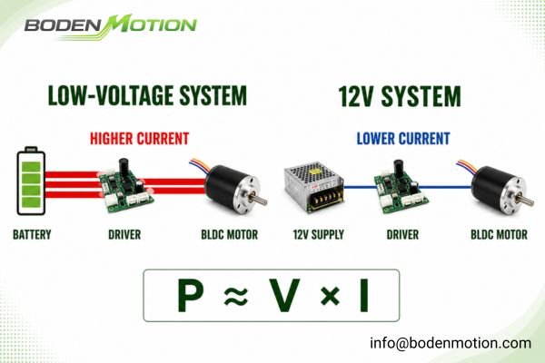
For similar delivered power and comparable system efficiency, a lower bus voltage generally requires higher bus current. This relationship (Power ≈ Voltage × Current) directly impacts wiring losses, driver stress, connector selection, and battery runtime. The choice between a low-voltage motor and a 12V motor is therefore a system design decision, not just a component selection.
From an integration perspective, there is no single "best" voltage. A low-voltage architecture simplifies power delivery in small, battery-powered devices. A 12V architecture often provides more manageable electrical conditions for moderate loads and continuous operation1. This article breaks down the engineering trade-offs to help you select the voltage platform that ensures reliable performance within your specific application.
What Is a Low Voltage Brushless DC Motor?
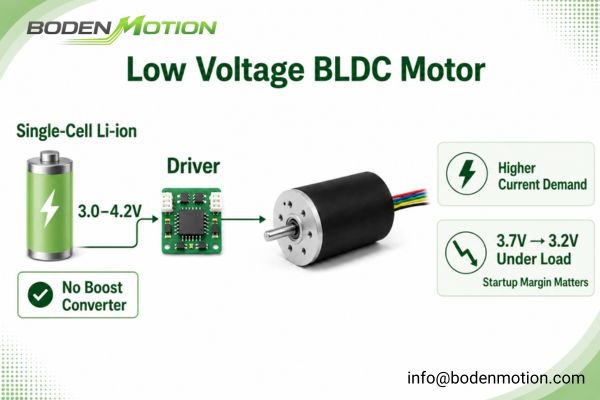
For a compact, portable device powered by a single-cell Li-ion battery, a low-voltage BLDC motor is often the default starting point. Its design simplifies the power architecture by avoiding the need for voltage-boosting circuits.
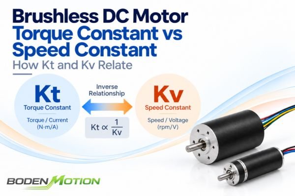
Compared with higher-voltage winding versions of the same motor platform, low-voltage versions are typically wound with fewer turns of thicker wire. This generally produces lower winding resistance, a higher velocity constant (Kv), and a lower torque constant (Kt). This design allows the motor to draw the high current needed for torque production, but it also places greater demands on the entire current path—from the battery and PCB traces to the connectors and motor driver.
While often used in lower to medium power ranges, higher power is technically feasible but places much greater demands on the system's current-carrying capacity and thermal management2.
Common applications include:
- Portable medical instruments
- Small robotic end-effectors
- Handheld analysis devices
- Battery-operated consumer electronics
- Compact cooling fans
System-Level Observation: A recurring issue in battery-powered projects is designing for the battery's nominal voltage (e.g., 3.7V) while overlooking the voltage sag under load3. A motor that starts reliably at 3.7V may fail when the battery voltage drops to 3.2V, a critical detail for ensuring consistent startup performance.
What Is a 12V BLDC Motor?
When an application requires running for extended periods, starting a pump under pressure, or driving a fan with consistent airflow, a 12V system provides a more electrically manageable power foundation.
A 12V BLDC motor is designed to operate from a standard 12V DC power system, a common voltage in industrial, automotive, and consumer electronics. This standardization offers integration advantages, including a mature ecosystem of components.
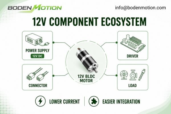
For similar input power, a 12V motor requires substantially lower bus current than its low-voltage counterpart. This reduces resistive losses (I²R) in wiring, connectors, and PCB traces, leading to easier thermal management and improved electrical efficiency in the power distribution path. OEM engineers also have access to a wide variety of off-the-shelf 12V power supplies, drivers, and connectors, which can accelerate development.
This makes 12V a practical choice for devices that need more than minimal power, offering greater electrical headroom to handle startup torque and load fluctuations.
Typical applications include:
- Small diaphragm or peristaltic pumps
- Automation modules and compact actuators
- Medical device subassemblies (e.g., analysis machines)
- High-performance cooling fans and blowers
- Equipment powered by standard DC wall adapters
Key Differences Between Low Voltage BLDC Motors and 12V BLDC Motors
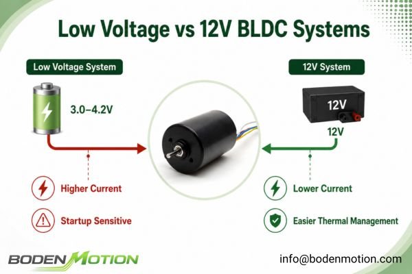
The following table compares how motor voltage affects bus current, wiring, thermal behavior, driver requirements, and startup conditions within the complete power system.
This comparison focuses on how the motor's voltage rating interacts with the power delivery system, helping to prevent common integration issues.
| Comparison Item | Low Voltage Brushless DC Motor | 12V BLDC Motor |
|---|---|---|
| Typical Voltage | 3V, 5V, 6V, or other low-voltage platforms | 12V DC system |
| Main Advantage | Simplified power architecture for battery devices | Easier electrical and thermal management |
| Bus Current Demand | Higher current for the same input power | Lower current for the same input power |
| Wiring Loss (I²R) | More sensitive due to higher current4 | Less sensitive due to lower current |
| Startup Margin | Requires careful management of source impedance | Often easier to manage with a suitable power source |
| Battery Compatibility | Well-suited for single-cell or low-series packs | Better for larger packs or multi-cell series |
| Thermal Risk | Higher bus current can cause localized heating in wiring, connectors, and driver.5 | Typically easier to manage at the bus level because of lower current. |
| Load Suitability | Commonly used for light to moderate loads when current and thermal limits are controlled. | Well-suited for moderate loads and continuous operation. |
| Driver Requirement | Low-voltage, high-current driver is essential | Wider range of standard drivers available |
| Best Selection Basis | Battery type, device size, and current limit | Load profile, duty cycle, and power stability |
Why Voltage Affects Current, Wiring Loss, and Heat
A motor's datasheet efficiency often overlooks the electrical losses in the rest of the system. The choice of bus voltage is a primary factor in these "hidden" losses.
For the same electrical input power, a lower voltage system must supply higher current. This increases resistive heating (I²R loss) in every part of the current path: wires, connectors, PCB traces, and driver MOSFETs.
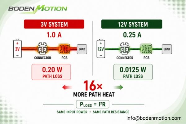
This simplified example compares power-distribution losses only, assuming the same electrical input power and the same path resistance. It does not represent total motor efficiency, winding loss, or driver loss. Consider a system requiring 3W of electrical input power with a total power-path resistance of 0.2 ohms:
- 12V System: Current = 3W / 12V = 0.25A
- Path Loss = (0.25A)² × 0.2Ω = 0.0125W
- 3V System: Current = 3W / 3V = 1.0A
- Path Loss = (1.0A)² × 0.2Ω = 0.2W
In this scenario, the 3V system generates 16 times more heat in its power distribution path. This wasted energy is not just a drain on the battery; it's heat that can potentially increase local component temperature and long-term thermal stress6.
How Voltage Selection Affects Startup Margin and Load Response
Startup is one of the most common stages at which integration problems become visible. The motor must overcome static friction and load inertia, a process that demands a peak level of torque and therefore a peak level of current.
Startup torque is a function of the motor's torque constant (Kt) and the actual phase current (Torque ≈ Kt × Current), which is limited by the motor's winding resistance, the driver's current limit, the power source's impedance, and the control strategy. A higher bus voltage does not inherently mean higher startup torque, as 12V and 3V motors have very different winding designs.
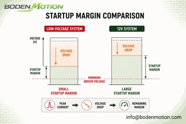
The primary advantage of a 12V architecture is that it provides more electrical headroom. When the power source, driver, and wiring are correctly sized, the lower bus current can help maintain a more consistent voltage at the motor-driver input during the high-demand startup phase7. This stability gives the driver more headroom to regulate current effectively and makes the system less sensitive to variations in battery charge level, temperature, and mechanical load.
In one portable pump project, a longer production wire harness and normal battery variation reduced the voltage available during startup. Moving to a higher-voltage architecture with a properly sized converter improved the startup margin and reduced the intermittent startup failures observed during validation.
What OEM Buyers Should Confirm Before Choosing Motor Voltage
An effective motor selection process begins with a clear definition of the system's operating reality, not just the component's price. The motor's voltage rating is a commitment to a specific power architecture.
Before choosing, you must have clear answers about the power source and the load it will face. This information is more valuable than any single number on a motor's datasheet.
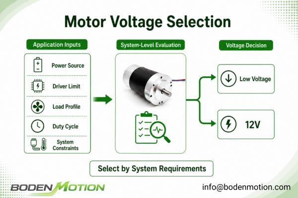
At BODENMOTION, we help OEM clients analyze these factors to make an informed decision. An effective technical discussion requires the following inputs:
- Power Source: Minimum and maximum supply voltage, battery chemistry, or power supply model.
- Driver: The specific driver IC or module and its current limit settings.
- Load Profile: Startup torque, running torque, and any load variations.
- Duty Cycle: Continuous or intermittent operation, with on/off timing.
- System Constraints: Wire length, connector type, ambient temperature, and available space.
The appropriate voltage platform depends on the application's dominant constraints, including battery configuration, load profile, wiring length, duty cycle, current limit, and available thermal margin.
Application Selection Guide: Low Voltage BLDC Motor or 12V BLDC Motor?
The following guide helps OEM teams make an initial assessment based on common application requirements.
Use it to frame your design discussions before finalizing your power architecture.

| Application Requirement | Better Option | Reason |
|---|---|---|
| Small, Single-Cell Battery Device | Low Voltage BLDC Motor | Simplifies power architecture; avoids DC-DC converter. |
| Light Load, Intermittent Use | Low Voltage BLDC Motor | Sufficient performance with lower system complexity. |
| Pump or Fan Startup Under Load | Often 12V BLDC Motor | Lower bus current and greater voltage headroom can ease startup. |
| Moderate or Continuous Operation | 12V BLDC Motor | Easier thermal management due to lower I²R losses in the path. |
| Long Wiring Harness or Connectors | 12V BLDC Motor | Lower bus current minimizes voltage drop and connector heating8. |
| System Already has a 12V Rail | 12V BLDC Motor | Leverages existing power supply, simplifying integration. |
| Strict Current Limit from Source | Depends on System Design | A 12V motor may draw less current for the same output power. |
| Low Noise Requirement | Depends on Motor & Driver | Voltage is not a primary factor; build quality and control matter more. |
Design Trade-Off: If your device is battery-powered but needs the stability of a 12V motor, you must budget for a DC-DC boost converter. This adds cost, complexity, and a small efficiency loss. However, this is often a better trade-off than struggling with the tight electrical margins of an under-powered low-voltage system.
Conclusion
Motor voltage is a system design choice with far-reaching consequences. Low-voltage and 12V BLDC motors are optimized for different application boundaries, and a successful selection depends on a full system analysis.
Low-voltage systems excel in compact, battery-powered devices with simple power architectures and light loads. 12V systems provide an easier path to managing the electrical and thermal loads of more demanding applications. The optimal choice is the one that provides sufficient performance margin within your project's specific power, thermal, and cost constraints.
If you are developing an OEM device, our engineering team can help you evaluate the trade-offs. Provide us with your operating parameters—including supply voltage range, battery type, driver current limit, startup torque, duty cycle, and ambient temperature—at info@bodenmotion.com. We can use these parameters to compare suitable winding, voltage, driver, and power-supply options for prototype evaluation.
FAQ
Q1: What is the difference between a low voltage brushless DC motor and a 12V BLDC motor?
A low voltage brushless DC motor usually operates below 12V (e.g., 3V, 5V) and is common in compact, battery-powered devices. A 12V BLDC motor operates from a 12V system and typically makes it easier to manage the electrical and thermal loads of applications requiring more power or continuous operation.
Q2: Is a lower voltage BLDC motor always safer?
Lower voltage may simplify insulation and electrical protection requirements in some compact devices, but it does not eliminate current-related heating risks in wiring, connectors, PCB traces, or driver components.
Q3: Why can a 12V BLDC motor be easier to start reliably?
A 12V system, with its lower bus current for a given power level, typically suffers less voltage drop across the wiring and power source. This provides more stable voltage headroom for the driver to control the motor during the high-demand startup phase.
Q4: Which motor is better for battery-powered devices?
It depends on the load and runtime. For small, light-load portable devices, a low-voltage motor often simplifies the design. For devices with higher loads or tighter startup margins, a 12V architecture may provide more manageable bus current and startup conditions, provided any converter and driver are correctly sized.
Q5: What should OEM buyers provide before choosing motor voltage?
Provide the minimum and maximum supply voltage, battery chemistry or power-supply model, driver current limit, startup load, running torque, target speed, duty cycle, wire length, and ambient temperature.
"What Is a 12V DC Power Supply? Basic Guide - Ventron", https://www.ventronchip.com/news/what-is-a-12v-dc-power-supply-basic-guide.html. Engineering sources and technical standards indicate that 12V architectures are widely used for moderate loads and continuous operation due to their balance between safety and efficiency, supporting the claim about their manageability in such scenarios. Evidence role: general_support; source type: education. Supports: A 12V architecture often provides more manageable electrical conditions for moderate loads and continuous operation.. Scope note: The support is based on common engineering practice and may not account for all possible load conditions or specialized applications. ↩
"Topology, design, analysis and thermal management of ...", https://chrismi.sdsu.edu/publications/2008_1_3_IJEHV_Topology_design_PE.pdf. Technical literature on power electronics explains that increasing power levels in electronic systems necessitates enhanced current-carrying capacity and improved thermal management to prevent overheating and ensure reliability. Evidence role: mechanism; source type: education. Supports: higher power is technically feasible but places much greater demands on the system's current-carrying capacity and thermal management.. Scope note: This support is general to electronic systems and may not address all specific device types. ↩
"Battery Voltage Sag", https://support.ride1up.com/support/solutions/articles/65000186153-battery-voltage-sag. Engineering resources on battery-powered device design highlight that voltage sag under load is a common challenge, and designing solely for nominal voltage can lead to unreliable device operation. Evidence role: general_support; source type: education. Supports: A recurring issue in battery-powered projects is designing for the battery's nominal voltage (e.g., 3.7V) while overlooking the voltage sag under load.. Scope note: The prevalence of this issue may vary by application and design experience. ↩
"DC Wiring Losses", https://pvpmc.sandia.gov/modeling-guide/3-dc-array-iv/dc-wiring-losses/. Standard electrical engineering references explain that wiring losses, calculated as I²R, increase with higher current, making low-voltage systems more sensitive to such losses. Evidence role: mechanism; source type: education. Supports: More sensitive due to higher current. Scope note: The explanation is based on general electrical theory and may vary with specific motor and wiring configurations. ↩
"UL & NEC Conductor and Connector Temperature Rise", https://lugsdirect.com/UL_TemperatureRatings60C_75C_90C_105C.htm?srsltid=AfmBOoo20uNk89wYk6ESOS3_ax-A8sqAwx4fvJmhCnLEH6FhtT7Eh0sn. Research literature on electrical engineering and motor design indicates that higher current in low-voltage systems increases the risk of localized heating in wiring, connectors, and drivers due to resistive losses (I²R). Evidence role: mechanism; source type: education. Supports: Higher bus current can cause localized heating in wiring, connectors, and driver.. Scope note: This general principle applies to electrical systems and is not exclusive to BLDC motors. ↩
"Understanding Joule Heating: Why Resistance Makes ...", https://meltric.com/news/2025/04/25/understanding-joule-heating-why-resistance-makes-wires-hot/. Technical literature on electronics reliability indicates that increased heat dissipation in components can raise local temperatures and contribute to thermal stress, which may affect long-term reliability. Evidence role: mechanism; source type: paper. Supports: This wasted energy is not just a drain on the battery; it's heat that can potentially increase local component temperature and long-term thermal stress.. Scope note: The impact on thermal stress depends on system design, cooling, and component specifications. ↩
"Weeks 9-10: DC Motor Controller", http://fab.cba.mit.edu/classes/863.14/people/andrew_mao/week9/. Technical literature on DC motor systems explains that higher supply voltages allow for lower current for the same power, which reduces voltage drop across wiring and helps maintain voltage at the load during high current demand, such as startup. Evidence role: mechanism; source type: education. Supports: The lower bus current in a higher voltage system helps maintain a more consistent voltage at the motor-driver input during startup.. Scope note: This general principle applies to DC systems and may vary with specific system designs. ↩
"Joule heating", https://en.wikipedia.org/wiki/Joule_heating. Electrical engineering references confirm that lower current in wiring reduces voltage drop and connector heating, as both are proportional to the square of the current according to Ohm's Law and Joule's Law. Evidence role: mechanism; source type: education. Supports: Lower bus current minimizes voltage drop and connector heating. Scope note: This is a general principle and assumes similar wire gauge and connector quality. ↩