When a miniature brushless DC (BLDC) motor fails to start, runs erratically, or triggers a controller fault, an engineer's first instinct is often to reach for a digital multimeter. This versatile tool is excellent for initial troubleshooting, allowing for quick checks on the motor's basic electrical integrity without needing complex test benches.
A multimeter can help identify basic electrical problems, such as open circuits, gross phase-to-phase resistance imbalances, obvious winding-to-housing conductive paths, and basic Hall sensor supply or output issues. However, these static checks cannot reliably detect minor turn-to-turn shorts or confirm whether a brushless motor can operate correctly under real-world dynamic conditions, such as producing the required torque at a specific speed or maintaining stability under load.
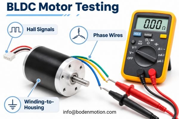
Furthermore, it is critical to distinguish between a bare BLDC motor and a motor with an integrated driver. A bare motor provides separate phase wires and, if equipped with Hall sensors, additional sensor wires for testing.1 By contrast, an integrated-driver motor typically exposes external power and control connections, while its phase and sensor connections are handled internally and may not be directly accessible. The test methods described here apply primarily to bare motors disconnected from their controllers.
Before Testing: Identify the Motor Wires and Prepare Safely
Before connecting any test probes, the first step is to correctly identify the motor's wiring and ensure the test can be performed safely. Applying the wrong test to the wrong wire can damage the motor, the controller, or the multimeter itself.
The tests described here fall into two categories: unpowered tests for electrical continuity and powered tests for sensor functionality. For all tests, the motor must be fully disconnected from its controller to prevent damage. Powered tests require a separate, correctly specified power supply.

Identify the Motor Architecture
First, confirm the motor's configuration. Common types include:
- Three-phase BLDC motor: Typically has three motor phase wires (U, V, W).
- Three-phase BLDC motor with Hall sensors: Has three phase wires plus additional wires for Hall sensor power and signals.
- BLDC motor with integrated driver: Wires are for power input and control signals (e.g., PWM, direction), not direct phase access.
| Wire Type | Typical Function |
|---|---|
| U / V / W | Three-phase motor connections |
| VCC | Hall sensor power supply (e.g., +5V) |
| GND | Hall sensor ground |
| HA / HB / HC | Hall position signals |
| PWM | Speed control input |
| FG | Speed feedback output (Frequency Generator) |
Real Integration Challenge: Wire color assignments can vary between motor and cable configurations2. Always refer to the motor's specific datasheet or wiring diagram. Assuming a color code is a common cause of misdiagnosis and component damage.
How to Check Phase Resistance and Continuity With a Multimeter
The most fundamental unpowered test is checking the phase-to-phase resistance between the motor's three phase wires. This helps identify open windings or significant imbalances.
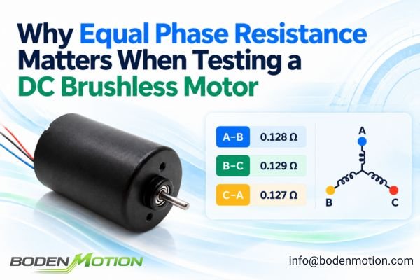
For a bare three-phase BLDC motor, the phase-to-phase resistance measured between any two phase terminals (U-V, V-W, W-U) should be reasonably close. This measurement primarily detects obvious open circuits and gross imbalances, but it cannot reliably identify subtle turn-to-turn shorts.

Measure Three Terminal Pairs
- Set the multimeter to its lowest suitable resistance range.
- Short the test probes together first to measure their own resistance. Use the meter's REL (relative) function if available to zero this out, or manually subtract this value from your measurements.
- Connect the probes across the first phase pair (e.g., U and V). Record the reading.
- Repeat for the other two pairs (V-W and W-U).
- Compare the three resistance readings.
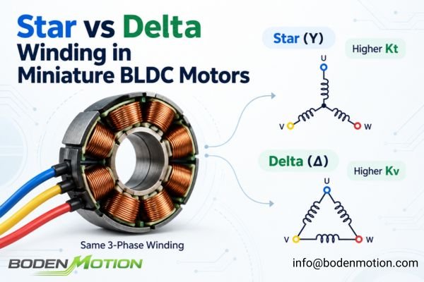
For a star-connected motor, the measured line-to-line resistance is the sum of two phase winding resistances.3 For a delta-connected motor, the relationship is different. In a balanced delta-connected motor, the measured line-to-line resistance is the equivalent resistance of one winding branch in parallel with the other two branches in series. Therefore, it is not equal to the resistance of a single winding branch. The key is consistency between the three readings, not the absolute value itself unless compared against a manufacturer's specification. For the very low resistance values common in miniature motors, a four-wire Kelvin measurement is the most accurate method.
What Do the Results Mean?
| Measurement Result | Possible Interpretation |
|---|---|
| All readings are reasonably close | No obvious phase resistance imbalance detected. |
| OL (Over Limit) on one or more pairs | Possible open winding or disconnected lead. |
| One pair has significantly higher resistance | Possible poor connection or winding abnormality. |
| One pair has significantly lower resistance | Possible winding abnormality or measurement issue. |
| Readings fluctuate | Unstable probe contact or an intermittent connection. |
How to Check for a Short Circuit Between the Winding and Motor Housing
This unpowered test checks for an insulation failure where a motor winding has made electrical contact with its metal case.
A standard multimeter in resistance or continuity mode can detect an obvious, low-resistance path between a winding and the motor case. However, an Over Limit (OL) reading does not prove the insulation is healthy, as a multimeter cannot perform a true insulation resistance test.

Basic Multimeter Check
With the motor fully disconnected:
- Set your multimeter to a high resistance range or continuity mode.
- Place one probe firmly on a motor phase terminal (e.g., U).
- Place the other probe on an unpainted, conductive part of the motor housing.
- The reading should ideally be OL, indicating no obvious continuity.
- Repeat for the other phase terminals (V and W).
Interpreting the Results
| Result | Possible Meaning |
|---|---|
| OL / No continuity | No obvious low-resistance conductive path was detected. |
| Low resistance / Beep | Possible winding-to-case short circuit; insulation may be compromised. |
Common OEM Mistake: Assuming a multimeter "OL" reading proves good insulation. A multimeter uses a very low test voltage. A formal insulation resistance test uses a specified, higher DC test voltage selected according to the motor manufacturer's specifications and insulation requirements. Applying high voltage from an insulation tester without isolating Hall sensors or integrated electronics can damage or permanently destroy them.
How to Test Hall Sensors in a Mini Brushless Motor
This is a powered test. Hall sensors provide rotor position feedback to the controller for electronic commutation. If they fail, the motor may not start or may run erratically.
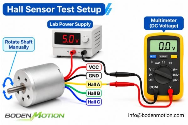
Testing Hall sensors with a multimeter involves two steps: first, confirming they receive the correct supply voltage, and second, checking that their output signals change state as the motor shaft is manually rotated. This test confirms basic low-speed functionality but not high-speed performance or timing.
Check Hall Sensor Supply Voltage
- Connect the motor's Hall sensor VCC and GND wires to a current-limited power supply set to the correct voltage (typically +5V, but always check the datasheet).
- Use the multimeter in DC voltage mode to measure between the VCC and GND pins to confirm the supply voltage is present and correct.
Check Hall Signal Outputs
- With the sensors powered, connect the multimeter's negative probe to the Hall GND.
- Connect the positive probe to the first Hall signal output (e.g., HA).
- Slowly and smoothly rotate the motor shaft by hand.
- Observe the multimeter display. The voltage should switch between a low state (near 0V) and a high state. The high state voltage depends on the output type.
- Repeat for the other two signals (HB and HC).
Some Hall sensors have open-collector or open-drain outputs, which require an external pull-up resistor (e.g., 1-10 kΩ) connected between the signal line and VCC to produce a high state.4 Others have push-pull outputs and do not require one. A multimeter's slow refresh rate may not catch all transitions, so an oscilloscope is the preferred tool for a thorough analysis.
What Can Manual Shaft Rotation and Back-EMF Checks Reveal?
Simple mechanical and electrical checks performed while turning the shaft are unpowered tests that can offer additional clues about the motor's condition.
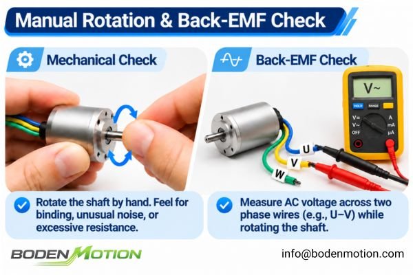
By manually rotating the shaft, you can feel for mechanical issues and check for the generation of back-EMF. Detecting a generated voltage indicates the motor produces an induced voltage, but a basic multimeter reading cannot validate the health of the rotor magnets or the full integrity of the windings.
Check Mechanical Rotation
With the motor disconnected, turn the output shaft slowly by hand. You should feel for:
- Mechanical binding or seizure: The shaft should rotate smoothly.
- Rubbing or scraping noises: Could indicate internal interference or bearing damage.
- Excessive rotational resistance: Could point to contaminated bearings or internal issues.
Note that some resistance from magnetic detent torque (cogging) is normal in many BLDC motor designs5 and should not be mistaken for a fault.
Check Generated Voltage (Back-EMF)
- Set your multimeter to AC or DC voltage mode.
- Connect the probes across two phase wires (e.g., U and V).
- Rotate the motor shaft steadily by hand.
- You should see a small voltage generated. Comparing the voltage generated across all three phase pairs (U-V, V-W, W-U) at a consistent speed can help identify an obvious open phase. However, a multimeter cannot validate the back-EMF waveform shape, amplitude, or phase relationships, which requires an oscilloscope.
How to Interpret Multimeter Results When Troubleshooting Motor Failures
A single test result is rarely enough for a diagnosis. Combining the findings from all checks provides a much clearer picture of the potential fault.
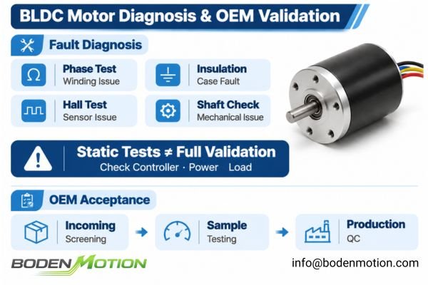
A normal static electrical test does not prove that the motor, controller, and load are functioning correctly as a system. Troubleshooting requires correlating the multimeter results with the observed failure symptom to narrow down the problem.
| Observed Symptom | Possible Cause | Recommended Next Check |
|---|---|---|
| Motor won't start; one phase pair reads OL | Open winding or disconnected lead | Check phase wiring and re-measure continuity. |
| One phase pair has abnormal resistance | Winding damage or poor connection | Repeat low-resistance measurement carefully. |
| Phase terminal shows continuity to housing | Potential insulation failure | Confirm with an appropriate insulation tester. |
| Hall supply voltage is missing | Power supply or wiring problem | Check power source and all connections. |
| One Hall signal does not change state | Faulty sensor, wiring, or pull-up circuit issue | Check Hall circuit and inspect the signal waveform with an oscilloscope. |
| Shaft feels mechanically restricted | Damaged bearing or mechanical interference | Inspect shaft, bearings, and mechanical assembly. |
| All static tests appear normal, but motor fails | Driver, commutation, power supply, or load issue | Check controller, phase signals, and operating current. |
| Motor runs but overheats | Excessive current, overload, or thermal issue | Measure operating current, voltage, and temperature rise. |
Why Static Electrical Tests Are Not Enough for OEM Acceptance
For an OEM, multimeter tests are a useful but limited tool.
- Incoming Inspection: Basic resistance and continuity checks can screen for obvious manufacturing defects such as open circuits, gross phase-to-phase resistance differences, and obvious winding-to-housing conductive paths when receiving a new batch of motors.
- Sample Approval: Approving a motor for a new design requires more than static electrical checks. It also requires dynamometer-based testing to measure torque and speed under an applied mechanical load6, providing performance data that resistance and continuity measurements alone cannot supply.
- Mass Production: Consistent electrical test results can be part of a quality control process, but they must be correlated with functional performance criteria to be meaningful.
What a Multimeter Cannot Prove—and When Advanced Testing Is Needed
The most important part of using a multimeter is understanding its limitations. It is a tool for finding basic electrical faults, not for comprehensive performance validation.
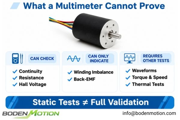
A multimeter is an excellent starting point, but it cannot definitively prove a motor is "good." A motor that passes all static multimeter tests can still fail under dynamic load due to issues that only more advanced equipment can detect.
What a Multimeter Can Check
- Basic winding continuity and open circuits.
- Approximate phase-to-phase resistance.
- Obvious low-resistance winding-to-housing paths.
- Hall sensor DC supply voltage.
- Basic Hall output transitions at very low speeds.
What a Multimeter Can Only Indicate
- Possible winding imbalance that requires confirmation with a micro-ohmmeter.
- Possible Hall sensor malfunction that requires waveform analysis with an oscilloscope.
- Basic back-EMF generation that is only qualitative.
What Requires Other Testing Equipment
| Testing Requirement | Recommended Equipment |
|---|---|
| Accurate low-resistance measurement | Four-wire micro-ohmmeter |
| Insulation resistance verification | Insulation resistance tester (Megger) |
| Hall signal timing and phase relationship | Oscilloscope |
| Back-EMF waveform shape and amplitude | Oscilloscope |
| Phase current and commutation behavior | Current probe and oscilloscope |
| Speed, torque, and efficiency performance | Motor dynamometer test bench |
| High-speed vibration and balance | Vibration analyzer / balancing equipment |
| Temperature rise under load | Temperature sensors and test bench |
Ultimately, a multimeter cannot prove rotor dynamic balance, high-speed stability, actual torque-speed capability, or whether the motor will meet its performance targets under a real-world load. This requires dynamic testing that simulates the motor's actual operating environment.
Conclusion
A multimeter is an indispensable first-line diagnostic tool for troubleshooting a mini brushless motor. It empowers engineers to quickly identify obvious electrical abnormalities such as open windings, significant phase resistance differences, obvious winding-to-housing conductive paths, and basic issues with Hall sensor power or output. These simple checks can often help narrow down the root cause of a failure without requiring a full system teardown.
However, for a reliable diagnosis, it is crucial to understand what a multimeter cannot prove. Passing static resistance and continuity checks does not guarantee a motor will start reliably, produce the required torque, maintain stable speed, or operate safely at high RPM. Engineers should always combine multimeter findings with mechanical inspection and be prepared to use more advanced tools when a problem is not immediately obvious. Exploring different architectures, including various Coreless Motors, requires a full understanding of both static and dynamic properties. For support, contact our engineering team at info@bodenmotion.com.
FAQ
Q1: Can you test a brushless motor with a normal multimeter?
Yes. A multimeter can check winding continuity, approximate phase-to-phase resistance, obvious low-resistance paths to the motor housing, and Hall sensor DC voltage signals. It cannot, however, formally verify insulation integrity or dynamic motor performance.
Q2: What resistance should a mini brushless motor have between its phases?
There is no single universal value. Resistance depends on the motor size, winding design (wire gauge, turns), and configuration (star vs. delta). The key is that the three phase-to-phase readings should be nearly identical and align with the manufacturer's specifications.
Q3: Can a multimeter detect a shorted BLDC motor winding?
A multimeter may reveal a gross resistance abnormality or an obvious low-resistance path between a winding and the motor housing. However, it usually cannot reliably detect minor turn-to-turn shorts because their effect on overall DC resistance may be too small for a standard two-wire meter to resolve.
Q4: How do you test Hall sensors with a multimeter?
After supplying the sensors with their specified voltage, connect the meter between each signal output and ground. Slowly rotate the motor shaft and observe if the voltage switches state. Note that open-collector or open-drain outputs may require a pull-up resistor to show a high state, while push-pull outputs normally do not.
Q5: Can a multimeter determine whether a BLDC motor is "good"?
No. Passing static electrical measurements does not prove that the motor can deliver its rated torque, speed, efficiency, or lifetime under actual operating conditions. A "good" motor is one that meets all performance requirements in its application.
Q6: What equipment is needed for more advanced BLDC motor testing?
Depending on the fault, engineers may need an oscilloscope (for waveforms and timing), a four-wire micro-ohmmeter (for precise resistance), an insulation resistance tester, a current probe, or a full motor performance test bench (dynamometer).
BLDC.com, motor wiring reference. The wiring reference illustrates the typical phase connections and Hall sensor wiring available on bare sensored BLDC motors. It supports the distinction between accessible motor leads for testing and integrated-driver connections. Scope note: Additional Hall sensor wires are present only on motors equipped with Hall sensors. ↩
Aerotech, "Brushless Motor Connections." The technical manual lists four different wire-color sets for Aerotech-supplied brushless motor cables, demonstrating that wire assignments can vary between cable configurations. It supports the recommendation to identify motor connections using the specific wiring documentation rather than assuming a universal color convention. ↩
Khan Academy, "Delta-Wye Resistor Networks." The educational material explains the equivalent resistance relationships of star (wye) and delta resistor networks. It supports the explanation that, for a star-connected motor, the measured line-to-line resistance is the sum of two phase winding resistances. This is a general circuit principle applied to motor winding measurements. ↩
Allegro MicroSystems, "Latching Switch Hall-Effect IC Basics." The application note explains the use of pull-up resistors in digital Hall-effect sensor circuits and identifies 1–10 kΩ as a common resistance range. It supports the explanation of Hall sensor output requirements and pull-up resistor selection. The actual resistance depends on the sensor's output current capability and supply voltage. Push-pull outputs generally do not require an external pull-up resistor. ↩
Magnequench, "Understanding and Manipulating Cogging Torque in Permanent Magnet Brushless DC Motors with Isotropic Bonded Magnets." The technical article explains how the interaction between rotor permanent magnets and stator structure produces cogging torque, and how magnet geometry and magnetic design influence its magnitude. It supports the explanation of magnetic detent resistance during manual shaft rotation. The presence and magnitude of cogging torque depend on the motor's design. ↩
Aaron Farley, University of Arkansas, "Design and Implementation of a Small Electric Motor Dynamometer for Mechanical Engineering Undergraduate Laboratory" (2012). The thesis describes a small electric motor dynamometer using a magnetic particle brake, load cell, torque arm, optical encoder, and data acquisition system. It presents actual torque-speed measurements under mechanical load and compares the experimental results with manufacturer-supplied data. It supports the use of dynamometer testing to evaluate motor torque and speed beyond basic static electrical checks. Scope note: The tested motor was a brushed permanent-magnet DC motor, not a BLDC motor. ↩