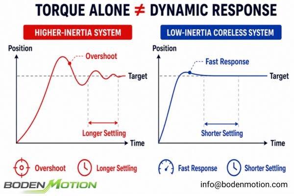
Selecting a motor based on torque alone often leads to disappointing performance in precision robotics. The actuator might be strong, but it feels slow, overshoots its target, or struggles with rapid, repetitive tasks.
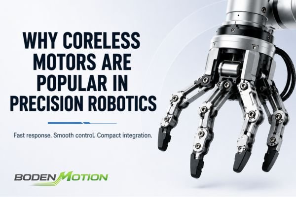
This happens because precision robotics depends more on dynamic response than on raw power. Coreless motors are popular in these applications because their low-inertia rotor structure enables rapid acceleration and responsive control, which are critical for fast and repeatable robotic motion cycles.
For a robotics engineer, a motor's datasheet is just the starting point. The real test is how the motor performs as part of a complete mechatronic system, including the drive electronics, control algorithms, gearing, and mechanical load. While coreless motors are not the default choice for every robotic axis—especially large, high-load base joints—their characteristics are exceptionally well-suited for dynamic, space-constrained actuators like grippers, wrists, and small joints. The exact construction differs between brushed coreless motors and ironless or slotless brushless designs, but this article focuses on their shared system-level advantages in robotics.
Why Low Rotor Inertia Matters in Robotic Motion
A robot joint rarely operates at one constant speed. It repeatedly accelerates, decelerates, stops, and changes direction, which means the motor's own rotational inertia becomes part of the load the actuator must move.
For high-dynamic robotic motion, lower rotor inertia means less torque is consumed accelerating the motor itself, leaving more of the available torque to accelerate the actual mechanical load.
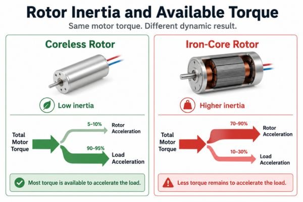
The relationship is governed by the basic equation of motion: Torque = Inertia × Angular Acceleration1 (T = Jα). This means that for a given acceleration (α), a motor with higher rotor inertia (J_rotor) requires more torque simply to get itself spinning. This "self-acceleration" torque is unavailable to move the robot's payload.
A motor with a higher torque-to-inertia ratio can therefore produce the rapid changes in motion that define a responsive robot. This directly improves the actuator's ability to:
- Accelerate and decelerate quickly.
- Reverse direction with less delay.
- Respond faster to control commands for error correction.
- Reduce settling time to stabilize at a target position.
How Fast Acceleration Improves Robot Cycle Time
In many robotic applications, the total time spent moving from point A to point B is dominated by acceleration and deceleration, not by cruising at top speed. A motor that can accelerate faster directly translates to a more productive robot.
Across selected coreless motor configurations we evaluate, the mechanical time constant—an indicator of intrinsic responsiveness—can be as low as approximately 1.9 ms under specified conditions. While the final robot cycle time depends on the complete system, this fast motor response is a critical enabler for reducing overall motion time.
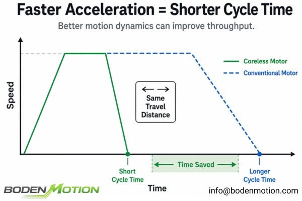
For a robot performing short, quick movements, the actuator may never even reach its top speed before it needs to start decelerating. In these cases, the ability to get up to speed quickly is far more valuable. When evaluating the total system, the required peak torque (T_peak) is approximately the sum of torque to overcome total inertia, friction, and gravity: T_peak ≈ J_total × α + T_friction + T_gravity2, where J_total includes motor inertia, transmission inertia, and the load inertia reflected to the motor shaft. By minimizing the motor's contribution to J_total, more torque is available for the task, enabling higher acceleration and shorter cycle times.3
Why Smooth Torque Helps Positioning and Force Control
Precision robots need to move not just quickly, but also with control. Smooth, predictable torque output is essential for tasks that require fine positioning, delicate handling, or precise force application.
The absence of cogging torque in coreless and ironless motor designs provides a smoother motion profile, which simplifies the control task for applications like gripper control, haptic feedback, and low-speed scanning.
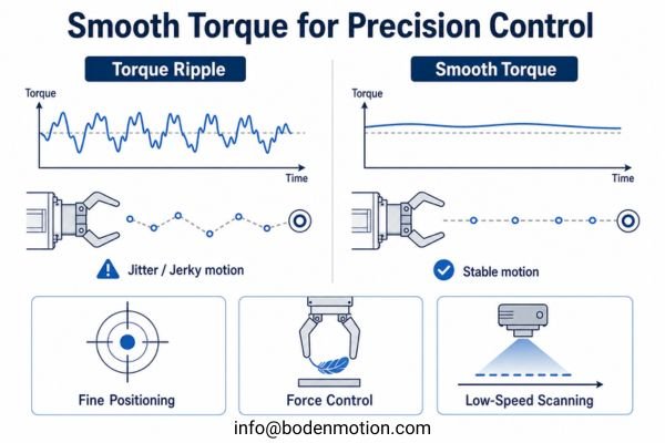
Cogging torque, caused by the magnetic interaction between rotor magnets and stator teeth in many iron-core motors, creates a ripple in the motor's output torque.4 This can cause jerkiness at low speeds and makes precise positioning more challenging. In coreless and ironless/slotless motor architectures, the conventional toothed magnetic structure responsible for cogging is removed, eliminating or greatly reducing this source of torque disturbance.5
This results in much smoother rotation, which is highly beneficial for:
- Fine Positioning: The actuator can make small, precise adjustments without being affected by magnetic detents.
- Force Control: In applications like robotic grippers or polishing tools, smooth torque output allows for more accurate and consistent force application.
- Low-Speed Scanning: For inspection or imaging tasks, smooth motion prevents jitter and ensures consistent velocity.
Real Integration Challenge:
A perfectly smooth motor does not guarantee a precise robot. Precision is a closed-loop system result. The final performance depends on integrating the motor with a suitable gearbox, a high-resolution encoder, and a well-tuned controller. However, starting with a responsive, cogging-free motor gives the feedback system a much cleaner platform to work with.
Why Compact Motor Mass Matters at the Robot Joint and End Effector
In robotics, where a motor is placed is just as important as what it can do. A heavy motor at the base of a robot is a stability problem; a heavy motor at the end of the robot's arm is a dynamics problem.
Using a lightweight, compact coreless motor in a robot's end-effector, gripper, or wrist joint reduces the overall moving mass. This effect is amplified because the inertia contributed by a distal mass is proportional to the square of its distance from the axis of rotation (J ≈ mr²).
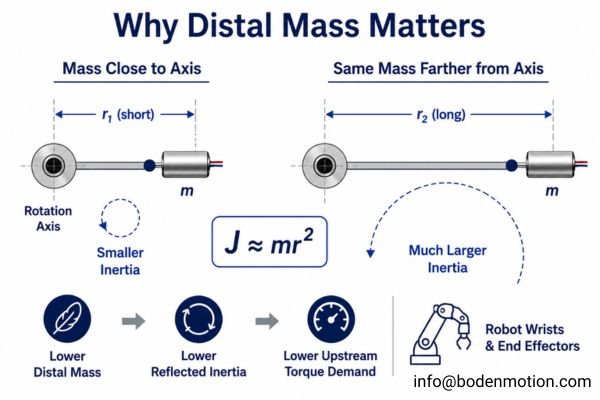
This system-level benefit is often overlooked. Every gram of mass you add to the end of a robotic arm has to be accelerated and decelerated by every joint between it and the robot's base6. For instance, a configuration like the BDCL1020 coreless brushless DC motor weighs approximately 8.5 grams with a rotor inertia of about 0.064 g·cm². Placing this low mass at the end of an arm has a far smaller impact on upstream joint torque requirements than a heavier motor would. This cascading effect means lower distal mass can lead to lower reflected joint inertia, reduced upstream torque demand, and potentially smaller and more efficient upstream actuators. This principle is critical in applications like dexterous robotic hands and surgical robots.
Coreless Motor vs Iron-Core Motor in Precision Robotics
After understanding the benefits, it's important to frame them in the context of engineering trade-offs. The choice between a coreless and an iron-core motor depends on which characteristics are most critical for a specific robotic axis.
For precision robotics, the choice often comes down to dynamic response versus continuous load capacity. A coreless motor excels at rapid, short-cycle motion, while a different motor architecture may be better for applications requiring sustained high torque.
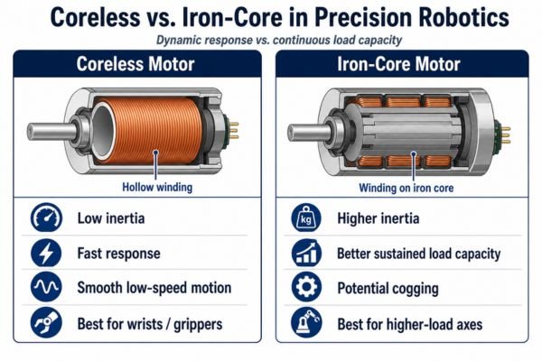
The distinction isn't about one being superior overall, but about making the right engineering choice for each joint. Here is a breakdown of their typical characteristics in a robotics context:
| Comparison Item | Coreless Motor | Traditional Iron-Core Motor |
|---|---|---|
| Rotor Inertia7 | Generally lower, supporting faster dynamic response. | Generally higher, requiring more torque for rapid acceleration. |
| Acceleration | Faster response is achievable due to lower rotational inertia. | Typically slower for the same available acceleration torque. |
| Cogging Torque8 | Absent or greatly reduced in coreless and ironless/slotless designs, depending on architecture. | May exhibit cogging due to interaction with the toothed magnetic structure. |
| Motion Smoothness | Well suited for fine positioning and controlled low-speed motion. | Smoothness depends more strongly on motor design and control compensation. |
| Size & Weight | Favorable power-to-weight characteristics in many compact designs. | Often larger or heavier for comparable dynamic performance. |
| Thermal Path | Continuous performance depends strongly on winding temperature, duty cycle, and the winding-to-housing heat path. | Larger structures may provide greater thermal mass and more favorable heat dissipation in some designs. |
| Typical Robotics Fit | Fast, lightweight, space-constrained motion such as grippers, wrists, and small precision joints. | Higher-load or less size-sensitive axes where sustained torque and thermal capacity are higher priorities. |
What OEM Engineers Should Confirm Before Selecting a Coreless Motor for Robotics
Simply asking for a motor with a certain torque and RPM is not enough to specify an actuator for a precision robotic application. A successful integration depends on understanding the entire motion profile and system constraints.
To ensure a coreless motor will meet your performance goals, you need to provide a complete picture of the application, from mechanical loads to thermal limits and control requirements.
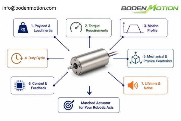
The most productive conversations about motor selection start not with a part number, but with the details of the robotic task. The goal is to match the complete actuator—motor, gearbox, and feedback system—to the application.
Before selecting a motor, be prepared to define the following parameters:
- Payload & Load Inertia9: What is the mass and inertia of the object being moved?
- Torque Requirements: What are the peak and continuous torque needs, including friction and gravity?
- Motion Profile: What is the target speed, acceleration/deceleration time, and travel distance or angle?
- Duty Cycle10: How frequently does the motion cycle repeat, and are there any holding periods?
- Mechanical & Physical Constraints: What is the available space, required gear ratio, and maximum allowable temperature?
- Control & Feedback: What type of driver and supply voltage will be used, and what encoder resolution is required?
- Lifetime & Noise: What are the operational life and acoustic noise requirements?
Coreless Motor Selection Guide for Precision Robotics
Choosing the right coreless motor involves matching its strengths to the top priorities of your specific robotic application. As with broader DC motor selection, the goal is not to find the "best" motor in isolation, but to match the motor and actuator architecture to the actual motion, load, thermal, and control requirements.
This guide helps connect common robotic requirements to the motor and system characteristics that matter most, shifting the focus from individual motor specs to the needs of the overall actuator system.
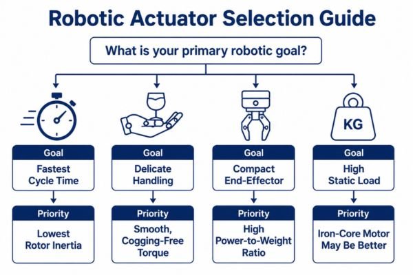
The table below offers a practical way to think about your design priorities. If your primary goal is reducing cycle time, rotor inertia becomes a critical parameter. If you are designing a compact robotic hand, motor mass is paramount.
| Robotic Requirement | Motor/System Priority | Why It Matters |
|---|---|---|
| Fast Pick-and-Place | Low rotor inertia | Reduces acceleration and deceleration time, increasing throughput. |
| Dexterous Robotic Hand | Small size + fast response | Allows for compact joints and supports frequent, agile finger movements. |
| Precision Gripper | Smooth low-speed torque | Helps with controlled gripping force and prevents damage to delicate objects. |
| Lightweight End-Effector | Low motor mass11 | Reduces the inertia and torque load on all upstream robotic joints. |
| Rapid Direction Reversal | High torque-to-inertia ratio | Improves dynamic response for tasks requiring agility. |
| High-Precision Positioning | Encoder + low-inertia motor | Enables a fast and stable closed-loop control system. |
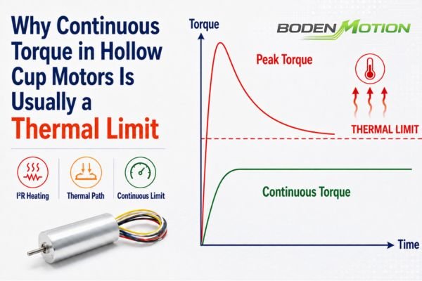
| High Repeated Cycle Rate | Thermal validation | Ensures the motor can handle heat generated from repeated acceleration. |
| High Payload Joint | Torque margin + gearbox matching | Dynamic response alone is not enough; the actuator must handle the static and dynamic loads. |
Conclusion
Coreless motors are popular in precision robotics because their low-inertia design directly addresses the core challenges of dynamic motion: the need for rapid acceleration, smooth control, and compact actuator mass. Their lightweight rotor allows them to respond quickly and efficiently, making them particularly well suited for the frequent start-stop cycles common in robotic joints, grippers, and end-effectors.
However, selecting a coreless motor does not guarantee a high-performance robot. The final system performance is determined by the integration of the motor with the gearbox, encoder, driver, and mechanical structure. For robotics OEMs, the right motor solution comes from a holistic analysis of the required motion cycle and payload. If you need support evaluating your robotic application's requirements, the engineering team at BODENMOTION is ready to assist. Contact us at info@bodenmotion.com.
FAQ About Coreless Motors in Robotics
Q1: Why are coreless motors used in robotics?
Coreless motors have low rotor inertia, which enables fast acceleration and deceleration. Their compact size, light weight, and smooth, cogging-free motion make them highly suitable for the dynamic and precise movements required in many robotic applications.
Q2: Are coreless motors better than iron-core motors for robots?
Not in every application. Coreless motors excel where fast dynamic response, low moving mass, and compact integration are the top priorities. Other motor architectures may be a better choice for applications where high continuous torque, thermal capacity, or lower cost is the primary concern.
Q3: Why is low inertia important in robotic joints?
Low rotor inertia allows the motor to accelerate, decelerate, and reverse direction more quickly because less torque is wasted on moving the motor's own rotor. This leaves more available torque to move the actual robotic load, resulting in a more agile and responsive system.
Q4: Do coreless motors need a gearbox in robotic applications?
Not necessarily, but gearboxes are very common in robotic actuator designs. Many coreless motors operate at relatively high speeds and produce lower torque at the motor shaft, so a planetary gearbox is often used to reduce output speed and increase output torque to match the requirements of the robotic joint. However, some applications may instead use direct drive, belt transmission, tendon or cable mechanisms, lead screws, or other transmission architectures.
Q5: What information should robotics OEMs provide when selecting a coreless motor?
To ensure a proper match, robotics OEMs should provide a complete application profile, including actuator size constraints, payload mass and inertia, required torque and speed, the full motion cycle (acceleration, travel, deceleration, dwell), gear ratio, encoder requirements, thermal limits, and expected lifetime.
"Moment of inertia", https://en.wikipedia.org/wiki/Moment_of_inertia. This equation is a standard result from classical mechanics, as described in physics textbooks and engineering references, and defines the relationship between torque, moment of inertia, and angular acceleration for rotating bodies. Evidence role: definition; source type: encyclopedia. Supports: The relationship is governed by the basic equation of motion: Torque = Inertia × Angular Acceleration (T = Jα). ↩
"How to calculate continuous and peak torque values for ...", https://www.motioncontroltips.com/how-to-calculate-continuous-and-peak-torque-values-for-servo-applications/. This equation is commonly used in robotics and motion control literature to estimate the peak torque required for actuators, accounting for inertia, friction, and gravity effects. It provides a simplified model for sizing actuators in dynamic applications. Evidence role: general_support; source type: education. Supports: The required peak torque for a robotic actuator can be estimated as the sum of torques needed to overcome inertia, friction, and gravity, as expressed in the given formula.. Scope note: The equation is a first-order approximation and may not account for all dynamic effects in complex systems. ↩
"Inertia Matching: Why Perfect Isn't Always Best - Linear Motion Tips", https://www.linearmotiontips.com/inertia-matching-perfect-isnt-always-best/. Educational resources on robotics and motion control explain that reducing the motor's inertia contribution to the total system inertia allows more of the actuator's torque to be used for accelerating the load, which can improve acceleration and reduce cycle times. Evidence role: mechanism; source type: education. Supports: Minimizing the motor's inertia contribution to the total system inertia allows more torque to be used for acceleration, supporting higher acceleration and shorter cycle times.. Scope note: The effect may vary depending on the specific robot configuration and application requirements. ↩
"Meaning and impact of "Cogging torque" and "Ripple torque"", https://support.maxongroup.com/hc/en-us/articles/6726327972252-Meaning-and-impact-of-Cogging-torque-and-Ripple-torque. Encyclopedic and technical sources describe cogging torque as a phenomenon in iron-core motors resulting from the interaction between permanent magnets on the rotor and the stator teeth, leading to periodic variations in output torque. Evidence role: mechanism; source type: encyclopedia. Supports: Cogging torque is caused by the magnetic interaction between rotor magnets and stator teeth in iron-core motors, creating a ripple in the motor's output torque. ↩
"Coreless motors vs. iron-core motors - Servotecnica", https://servotecnica.com/en/motori-coreless-vs-motori-ironcore/. Technical literature and motor design references indicate that coreless and slotless motor architectures lack the toothed stator structure, which significantly reduces or eliminates cogging torque compared to conventional iron-core motors. Evidence role: mechanism; source type: education. Supports: Coreless and slotless motor architectures remove the toothed magnetic structure, thereby eliminating or greatly reducing cogging torque.. Scope note: The degree of cogging reduction may vary depending on specific motor designs. ↩
"Robot Arm Dynamics and Control", https://ntrs.nasa.gov/api/citations/19740008732/downloads/19740008732.pdf. Standard robotics dynamics literature explains that any mass added to the distal end of a robotic arm increases the inertia that must be managed by all upstream joints, as described in the equations of motion for serial manipulators. Evidence role: mechanism; source type: education. Supports: Every gram of mass you add to the end of a robotic arm has to be accelerated and decelerated by every joint between it and the robot's base. ↩
"Why maxon Uses Coreless Motor Design In Precision Motion Control ...", https://www.electromate.com/news/post/coreless-vs-iron-core-why-maxon-uses-coreless-motor-design-in-precision-motion-control-applications. Engineering textbooks and motor manufacturer datasheets indicate that coreless motors generally have lower rotor inertia compared to traditional iron-core motors, which supports faster dynamic response in applications requiring rapid acceleration. Evidence role: statistic; source type: education. Supports: Coreless motors generally have lower rotor inertia, supporting faster dynamic response, while traditional iron-core motors generally have higher inertia, requiring more torque for rapid acceleration.. Scope note: Specific inertia values vary by model and manufacturer; the statement is a general trend rather than a universal rule. ↩
"Cogging torque - Wikipedia", https://en.wikipedia.org/wiki/Cogging_torque. Technical literature on electric motors, such as the IEEE GlobalSpec and educational resources, explain that coreless (ironless or slotless) motors typically exhibit little to no cogging torque due to the absence of iron teeth in the stator, while traditional iron-core motors can display cogging torque as a result of magnetic interaction with the stator slots. Evidence role: mechanism; source type: education. Supports: Cogging torque is absent or greatly reduced in coreless and ironless/slotless designs, depending on architecture, while traditional iron-core motors may exhibit cogging due to interaction with the toothed magnetic structure.. Scope note: This generalization may not apply to all motor designs, as some advanced iron-core motors use techniques to reduce cogging torque. ↩
"Actuator Selection Guide: Criteria, Sizing, and Cost-Benefit Analysis", https://www.rollon.com/ind/en/educationals/actuator-selection-sizing-cost-benefits/. Engineering sources such as robotics textbooks and technical standards describe payload and load inertia as critical parameters in motor and actuator selection, as they directly affect the required torque and dynamic response. Evidence role: expert_consensus; source type: education. Supports: Payload and load inertia are essential parameters to define before selecting a motor for a robotic application. ↩
"Motor Duty Cycles Explained: S1–S8 Classifications & Guide", https://www.kebamerica.com/blog/4-types-of-motor-duty-cycles-every-engineer-should-know/. Technical literature and engineering standards define duty cycle as a key factor in motor selection, influencing thermal performance and expected lifespan of the actuator. Evidence role: definition; source type: education. Supports: Duty cycle is a necessary parameter to define before selecting a motor, as it affects thermal and operational considerations. ↩
"End-Effector Technologies for Fruit Harvesting Robots - PMC - NIH", https://pmc.ncbi.nlm.nih.gov/articles/PMC13259546/. Robotics engineering sources explain that reducing motor mass in end-effectors decreases the inertia and torque requirements for upstream joints, improving overall system efficiency. Evidence role: mechanism; source type: education. Supports: Low motor mass reduces the inertia and torque load on all upstream robotic joints in lightweight end-effector designs.. Scope note: The impact may depend on the specific robot architecture and payload distribution ↩