Misinterpreting a motor's current ratings is a common engineering oversight that often leads to undersized drivers, unexpected thermal issues, or oversized, costly power systems.
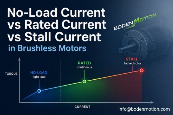
No-load, rated, and stall current are not just low, medium, and high values; they describe three different motor operating states—free-running, working under a specified continuous load, and being stopped under power—each requiring a different engineering decision.
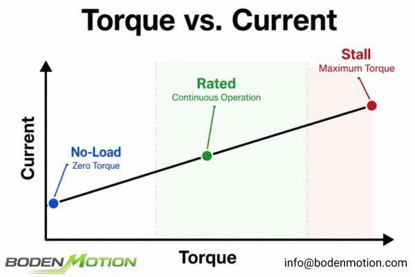
Many datasheets present these three values in a simple table, but they are not directly comparable. Each one is a snapshot of the motor's behavior under a unique set of electrical and mechanical conditions. Understanding what each value actually tells you is fundamental to designing a robust and reliable motion system, from selecting the right driver to implementing a safe fault-protection strategy.
What Is No-Load Current in a Brushless Motor?
When a motor is powered on and spinning freely without any external load, it still consumes a small amount of current. This is the no-load current.
It is the current drawn as the motor overcomes its own internal mechanical and electromagnetic losses at a specified voltage. While it seems minor, this value can be a useful diagnostic indicator.
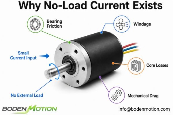
This current is used to overcome:
- Bearing Friction: The resistance from the ball or sleeve bearings.
- Windage: Air resistance acting on the spinning rotor, which increases with speed.
- Magnetic/Core Losses: Hysteresis and eddy-current losses in motor designs that use an iron magnetic core.
- Other Mechanical Drag: Resistance from seals or other internal components, if present.
Under consistent test conditions, no-load current is a useful production-trending and anomaly-screening parameter. If a motor shows a significantly higher no-load current than the established baseline for the same configuration and test method, it could indicate a bearing issue, rotor-stator interference, or an assembly misalignment. However, no-load current tells you nothing about how the motor will perform under real application load.
What Is Rated Current—and Can the Motor Run at It Continuously?
Your application requires the motor to run for hours at a time. The datasheet lists a "rated current," but is it safe to design your system around this single number?
Rated current is the current a motor is designed to handle continuously at its specified rated operating point without overheating. It should be treated as a continuous thermal reference under defined conditions, not as the default operating current for every application.
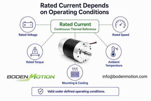
A rated current value is only meaningful when linked to the conditions under which it was measured:
- Rated Voltage: The supply voltage used for the test.
- Rated Torque: The continuous mechanical load applied to the shaft.
- Rated Speed: The resulting speed at the rated voltage and torque.
- Ambient Temperature: The surrounding air temperature (e.g., an illustrative condition of 25°C).
- Mounting & Cooling: Whether the motor was mounted to a heatsink or operating in free air.
The actual current your application will draw depends on its real torque-speed point, duty cycle, and thermal environment. If your application runs at a lighter load than the motor's rated point, its continuous current will be lower than the rated current. Conversely, operating in a high-temperature environment (e.g., 60°C) may require you to de-rate the motor and run it below its standard rated current to prevent overheating1.
What Is Stall Current in a Brushless Motor?
Imagine your robotic arm hits an obstacle. The motor stops turning, but the driver is still commanding it to move. The current demand spikes dramatically. This is the stall condition.
Stall current is the current drawn when the rotor is electrically powered but mechanically prevented from rotating. The motor determines the underlying electrical demand, while the driver and power system determine how much of that current is actually allowed to flow in a real system.
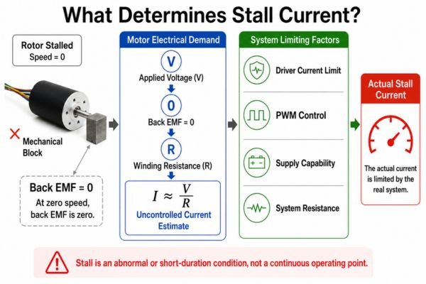
At zero speed, back EMF is zero, so the steady-state motor-side current is primarily constrained by winding resistance. A first-order estimate of uncontrolled stall current can be made with I ≈ V/R2, where V is the applied voltage and R is the relevant winding resistance at a specific temperature. The relevant resistance must also be interpreted correctly as phase or phase-to-phase resistance according to the motor's winding configuration and measurement method.
However, the actual current in a real BLDC system is also governed by:
- Electronic Current Limiting: The driver actively regulates current to a preset maximum.
- PWM Control: The drive strategy modulates the voltage applied to the windings.
- Power Supply Capability: The power supply voltage may droop under heavy load.
- System Resistances: Losses in wiring, connectors, and driver MOSFETs add to the total resistance.
Stall should be treated as an abnormal or short-duration condition, not as a continuous operating point. Sustained high current can rapidly overheat the windings and damage insulation. Under sufficiently severe thermal or current stress, permanent-magnet demagnetization may also become a risk3.
No-Load vs Rated vs Stall Current: What Does Each Value Actually Tell You?
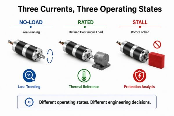
These three current values are not interchangeable points on a single scale; they represent three distinct operating states of the motor. Mistaking one for another is a frequent cause of design errors in OEM applications.
Each value is suited for a different engineering decision, from thermal management and driver sizing to fault protection analysis. Therefore, they must be interpreted based on the motor's mechanical state and the context of the measurement.
| Current | Operating State | Main Engineering Use | Suitable for Continuous Operation? | What It Does Not Prove |
|---|---|---|---|---|
| No-load current | Free-running without external load | Internal-loss trending and anomaly screening | Yes, under defined no-load conditions | Loaded torque or thermal capability |
| Rated current | Defined continuous operating point | Continuous thermal reference and operating-envelope evaluation | Yes, under specified rated conditions | Peak-current capability |
| Stall current | Rotor mechanically locked while powered | Peak electrical demand and fault/protection analysis | No | Continuous performance or efficiency |
Why Current Changes With Load, Speed, and Back EMF
Why can a motor's current draw vary so dramatically between these states? The answer lies in the interplay between torque, speed, and back electromotive force (back EMF).
In a simplified steady-state model, producing more torque to overcome a mechanical load requires the motor to draw more current. At the same time, the rotor's speed generates a back EMF that opposes the supply voltage, effectively limiting the current.
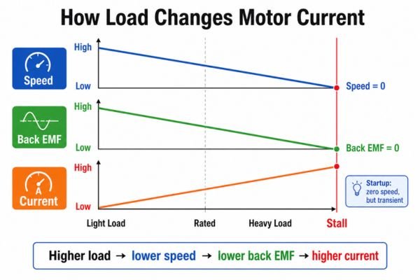
This dynamic creates a system where current changes with the operating condition:
- Light Load: The motor spins fast. High back EMF opposes the supply voltage, resulting in low current draw.
- Rated Load: The motor runs at a specified speed against a defined torque. Back EMF is lower than at no-load, allowing more current to flow.
- Heavy Overload: The load increases, slowing the motor further. Back EMF drops, and current rises significantly to produce more torque.
- Stall: The rotor stops. Back EMF is zero. Current demand spikes, limited only by the winding resistance and overall system constraints.4
Where Does Startup Current Fit?
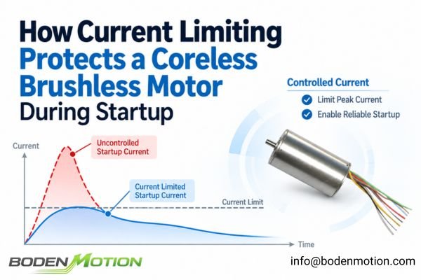
Startup occurs at zero speed, where back EMF is also zero. This means startup can involve a high current peak. However, startup current is not automatically equal to the published stall current5. It is a transient event influenced by:
- Load inertia and static friction
- The driver's acceleration ramp and current limit settings
- The power supply's ability to deliver a short-duration peak
Startup current is a critical parameter for ensuring your driver and power supply can handle the initial inrush without tripping fault protection or causing a voltage drop.
What OEM Buyers Should Confirm About Motor and Driver Current Limits
Before approving a motor, you must look beyond the motor datasheet and define the current requirements of the entire system. Simply matching a driver's rated current to the motor's is not enough.
A successful integration requires building a complete current profile for your application. In our OEM motor integration reviews, we normally build this application current profile before finalizing the driver.
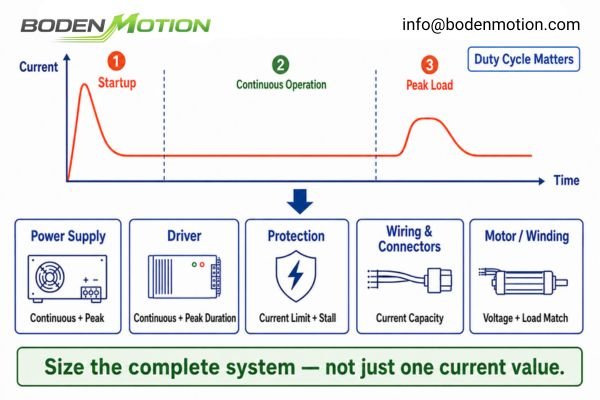
System Current Checklist:
- Power Supply: What are its continuous and peak current capabilities?
- Driver Sizing: What are its continuous and peak current ratings, and for how long can it sustain the peak?
- Current Limiting: At what level is the driver's current limit set? Is it adjustable?
- Application Load Profile: What is the current during startup, continuous operation, and peak load events?
- Duty Cycle: Will the motor run continuously or intermittently? This drastically affects thermal management.
- Protection: What is the strategy for stall detection and overcurrent shutdown?
- Wiring & Connectors: Are the wire gauge and connector ratings sufficient for both continuous and peak currents?
Current values should also be matched to the exact winding configuration being evaluated.6 BODENMOTION can evaluate application-specific voltage and winding configurations when the available DC bus voltage, driver current limit, or required torque-speed point does not align well with a standard winding.
Driver-Sizing Example: Which Current Should You Use?
Consider an illustrative BLDC datasheet containing no-load, rated, and stall current values that appear straightforward at first glance.
These values cannot be mechanically assigned to individual system components without first confirming the current definition and understanding the application's startup, continuous, and transient load profile.
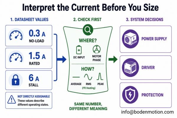
For this illustrative example, let's use the following values:
- No-load current: 0.3 A
- Rated current: 1.5 A
- Stall current: 6 A
Before using these values for system design, confirm where the current is measured—for example, at the DC supply or in the motor phases—and how the value is expressed, such as average, RMS, or peak current. These figures are not interchangeable.
One additional distinction matters when moving from datasheet values to component sizing: the current metric associated with torque production is not always the same one that determines winding heating.
System-Level Observation:
Winding copper heating is more closely related to RMS (Root Mean Square) current than average current.7 A drive with high current ripple will have a higher RMS current and therefore higherI²Rwinding losses for the same average torque output.8
With these distinctions established, each system component can be evaluated against the current information that is actually relevant to its function:
| Component / Function | Relevant Current Value(s) | Engineering Decision |
|---|---|---|
| Power Supply | Application Continuous & Peak DC Input Current | Must support the expected DC-side demand without excessive voltage droop during startup or transient load events. |
| Driver Continuous Rating | Application Continuous / RMS Current | Must handle the thermal load from the application's actual continuous RMS current. Use the motor's 1.5 A rated current as a thermal reference after confirming its definition is compatible with the sizing metric. |
| Driver Peak Rating | Startup & Peak Load Current | Must tolerate transient peaks required for acceleration and short-duration high loads. |
| Electronic Current Limit | Based on System Constraints | Set to a level that allows for necessary peak torque but protects the motor and driver from damaging overcurrent conditions. |
| Stall Protection Logic | Stall Current & Time | Uses current, time, and/or speed feedback to detect an abnormal locked-rotor condition and trigger a protective action. |
| Fuse / Upstream Protection9 | Max System Fault Current | Protects wiring and the power system against major short circuits or catastrophic failures; typically slower to react than electronic limits. |
Conclusion
No-load, rated, and stall current describe different operating states of a brushless motor and should not be used interchangeably. For OEM system design, each value should be interpreted together with startup behavior, continuous/RMS current, peak demand, and the actual load profile so the motor, driver, power supply, and protection strategy are sized correctly.
If you are developing an OEM motion system, BODENMOTION can help evaluate the application load profile, current requirements, and motor-driver matching to identify a suitable motor and control solution. Contact us at info@bodenmotion.com.
FAQ
Q1: What is the difference between no-load current and rated current?
No-load current is the current drawn when the motor runs without external mechanical load and must overcome its own internal mechanical and electromagnetic losses. Rated current is a continuous thermal reference defined under specified operating and thermal conditions.
Q2: Can a BLDC motor run continuously at stall current?
No. Stall should not be treated as a continuous operating condition. Sustained high current can rapidly overheat the windings and damage insulation; under sufficiently severe thermal or current stress, permanent-magnet demagnetization may also become a risk.
Q3: Should I size a BLDC driver according to stall current?
Not for the continuous rating. The driver's continuous rating should be based on the application's actual continuous/RMS current. The peak rating must handle startup and transient peaks. Stall current is primarily used for protection analysis and setting current limits.
Q4: Why can BLDC stall current be lower than the theoretical V/R value?
The actual system current can be lower because of factors like electronic current limiting in the driver, PWM voltage modulation, power supply voltage droop, and additional resistance from wiring and driver components. V/R is a simplified first-order estimate under defined zero-speed electrical conditions.
Q5: What current information should an OEM engineer provide to a motor supplier?
Provide the complete load profile: continuous torque and speed, peak torque and its duration, duty cycle, startup conditions (inertia, friction), and the ambient operating temperature. This allows the supplier to recommend a motor and winding that will perform reliably in your specific application.
"Extend the Operating Life of Your Motor", https://digital.library.unt.edu/ark:/67531/metadc831914/m2/1/high_res_d/1056708.pdf. Technical standards and engineering literature indicate that electric motors may require de-rating at elevated ambient temperatures to prevent overheating and ensure safe operation. Evidence role: mechanism; source type: education. Supports: operating in a high-temperature environment (e.g., 60°C) may require you to de-rate the motor and run it below its standard rated current to prevent overheating.. Scope note: The specific de-rating factor depends on the motor design and manufacturer guidelines. ↩
"Start vs. Stall Torque for Brushed and Brushless DC Motors", https://www.groschopp.com/start-vs-stall-torque-brushed-brushless-dc-motors/. Standard electrical engineering textbooks and motor control references describe that, at zero speed, the stall current of a DC or BLDC motor can be approximated by dividing the applied voltage by the total resistance of the windings, as back EMF is absent. Evidence role: mechanism; source type: education. Supports: A first-order estimate of uncontrolled stall current can be made with `I ≈ V/R`, where V is the applied voltage and R is the relevant winding resistance at a specific temperature.. Scope note: This is a simplified estimate and does not account for additional resistances or active current limiting in real systems. ↩
"Demagnetization analysis of outer-rotor-type BLDC motors ...", https://pubs.aip.org/aip/adv/article/14/2/025332/3265456/Demagnetization-analysis-of-outer-rotor-type-BLDC. Technical literature and motor design handbooks note that excessive current or temperature can cause partial or total demagnetization of permanent magnets in BLDC motors, especially under stall or overload conditions. Evidence role: mechanism; source type: education. Supports: Under sufficiently severe thermal or current stress, permanent-magnet demagnetization may also become a risk.. Scope note: The risk and threshold for demagnetization depend on magnet material and motor design. ↩
"Mystery Motor Data Sheet", https://hades.mech.northwestern.edu/images/6/61/Asst7.pdf. Standard electrical engineering references explain that at stall, a DC motor's back EMF is zero, and the current is determined by the supply voltage divided by the winding resistance, subject to system limitations. Evidence role: mechanism; source type: education. Supports: At stall, the rotor stops, back EMF is zero, and current is limited only by winding resistance and system constraints. ↩
"Start vs. Stall Torque for Brushed and Brushless DC Motors - Groschopp", https://www.groschopp.com/start-vs-stall-torque-brushed-brushless-dc-motors/. Technical literature notes that startup current in DC motors is a transient event and may differ from the steady-state stall current due to factors such as load inertia, driver settings, and power supply limitations. Evidence role: mechanism; source type: education. Supports: Startup current is not automatically equal to the published stall current; it is influenced by several transient factors.. Scope note: Sources may discuss typical differences but not provide a universal rule for all motor types. ↩
"Inductions Motors", https://energy.ece.illinois.edu/files/2016/10/9-16-16-induction-motor-seminar-handout.pdf. Technical references explain that matching current values to the specific winding configuration of a motor is essential for optimal performance and to prevent overheating or inefficiency. Evidence role: mechanism; source type: education. Supports: Current values should be matched to the exact winding configuration being evaluated.. Scope note: The importance of matching may depend on the motor design and application context. ↩
"Lesson 12. Power in AC Circuits", https://engineering.louisville.edu/raise/EE220/L12.html. Standard electrical engineering texts explain that winding copper losses are proportional to the square of the RMS current, not the average current, due to the nature of resistive heating (I²R losses). Evidence role: mechanism; source type: education. Supports: Winding copper heating is more closely related to RMS (Root Mean Square) current than average current.. Scope note: This relationship assumes the heating is dominated by resistive losses and does not account for other loss mechanisms such as core losses. ↩
"Impact of Current Pulsation on BLDC Motor Parameters - PMC", https://pmc.ncbi.nlm.nih.gov/articles/PMC7829742/. Research on motor drives shows that increased current ripple raises the RMS current, which in turn increases resistive (I²R) losses in the windings, even if the average current remains unchanged. Evidence role: mechanism; source type: research. Supports: A drive with high current ripple will have a higher RMS current and therefore higher `I²R` winding losses for the same average torque output.. Scope note: The impact depends on the specific waveform and drive topology; not all drives exhibit significant ripple. ↩
"Fundamentals of motor circuit protection - Consulting", https://www.csemag.com/fundamentals-of-motor-circuit-protection/. Electrical safety standards and technical literature describe that fuses and upstream protection devices are designed to protect against major faults and short circuits, and generally operate slower than electronic current limiting circuits. Evidence role: definition; source type: institution. Supports: Fuse or upstream protection protects wiring and the power system against major short circuits or catastrophic failures; typically slower to react than electronic limits.. Scope note: Response times and protection levels depend on the specific fuse type and system design. ↩