Selecting a coreless motor based on space constraints alone is a common path to system failure. The real goal isn't finding the smallest motor; it's finding the smallest one that can work reliably.
The right coreless motor size is the smallest one that can reliably meet the application's torque, speed, and duty cycle requirements while staying within its thermal and lifetime limits.
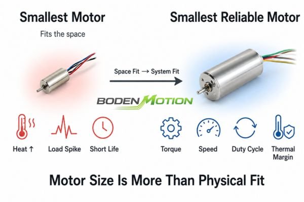
From my experience, motor sizing is where many compact device projects run into trouble. An engineer is pressured to shrink a mechanism, they pick a smaller motor that fits, and it works on the bench for a few minutes. But weeks later, during system integration or life testing, failures appear. The motor overheats, can't handle load spikes, or its bearings wear out prematurely. This is because motor sizing isn't just about a physical fit; it's a multi-variable engineering problem involving torque, inertia, speed, and, most importantly, heat.1
What Determines Coreless Motor Size?
A motor's physical dimensions are just the starting point. These dimensions directly influence its performance envelope, establishing the boundaries for its torque, thermal, and dynamic capabilities.
A motor's size is a proxy for its potential performance, defined by the electromagnetic volume and heat dissipation area, not just its physical footprint.
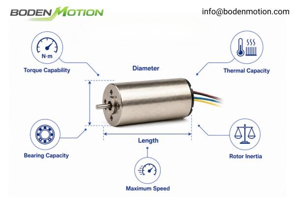
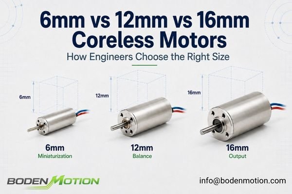
When we talk about a motor's "size," we're usually referring to its outer diameter and length. These two dimensions are among the primary geometric constraints on the motor's performance envelope. They affect:
- Torque Capability: Both peak and continuous torque relate to the volume of the motor's active materials (magnets and windings).
- Thermal Capacity: The motor's surface area and mass dictate how effectively it can dissipate heat.
- Rotor Inertia: The mass and diameter of the rotor determine its inertia, which affects acceleration and deceleration.
- Bearing Capacity: Diameter often dictates the size of the bearings, influencing load capacity and lifetime.
- Maximum Speed: Determined by rotor balance, bearing specs, and the back-EMF limit at a given voltage.
Across the BODENMOTION coreless motor platform, for instance, available diameters span from approximately 8 mm to 65 mm. However, this isn't a simple linear scale where "bigger is always better." A motor's final operating point is a complex result of its winding configuration, length, voltage, commutation type, and thermal environment.
How Coreless Motor Diameter and Length Affect Performance
Motor diameter and length are the two main levers an engineer can pull, but their effects are distinct. They define the design envelope, but the final performance characteristics are set by the specific configuration within that envelope.
The motor's geometry defines the available design envelope; the winding and configuration determine the actual operating characteristics within that envelope.
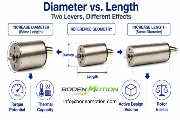
Diameter: The Foundation of Torque and Thermal Capacity
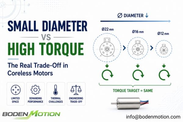
Increasing diameter is often the most effective way to boost a motor's fundamental torque-producing ability. A larger diameter increases the lever arm for magnetic forces and provides more volume for copper, directly improving torque output and thermal management.
Length: A Lever for Design Volume and Inertia
Within a comparable magnetic architecture and winding design, increasing the active motor length provides additional electromagnetic design volume and may increase torque capability, but it also increases rotor inertia. The final Kt, Ke, winding resistance, speed, and efficiency still depend strongly on the winding configuration and target operating point.
A Ø12 × 30 mm motor configured with a high-speed winding, for example, can perform very differently from the same motor envelope configured for a higher torque constant.
Key Engineering Insight:
Dimensions alone cannot predict final motor performance. Within a given diameter and length, factors like winding turns, wire gauge, magnet grade, and commutation type determine the final torque constant, resistance, efficiency, and speed. Always evaluate the specific motor configuration, not just the physical envelope.
Why Load Inertia and Speed Requirements Affect Motor Size Selection
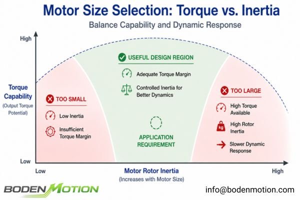
In dynamic applications, the battle is won or lost with inertia. A motor that can't effectively control the load's inertia will never deliver precise, responsive motion.
The motor must provide enough torque to accelerate not only the external load but also its own rotor. The inertia ratio between the motor and the load is critical for control stability and response time.
The total torque (T_accel) required for acceleration is:
T_accel = (J_motor + J_load) * α + T_friction + T_external
Where:
J_motoris the motor's rotor inertia.J_loadis the load's inertia as seen by the motor.αis the desired angular acceleration.
A load-to-motor inertia ratio of around 10:1 is sometimes used as an initial servo-sizing rule of thumb.2 It's not a universal stability limit, but a high ratio can make the system difficult to tune, often leading to overshoot and long settling times.3 The acceptable ratio depends heavily on mechanical stiffness, control bandwidth, and required performance. For high-response systems, a ratio closer to 5:1 or even 1:1 is often targeted.
This creates a balancing act for motor sizing:
- A very small motor has low inertia but may lack the torque to handle a high-inertia load, resulting in a poor inertia ratio.
- A very large motor has ample torque, but its own high rotor inertia may consume a large portion of that torque, limiting the system's dynamic response.
Why Thermal Performance Limits Miniature Coreless Motor Size
For continuous or high-duty-cycle operation, thermal performance often becomes the dominant limit on how small the motor can be. A motor that is too small for its thermal load is at high risk of failure.
A motor's continuous torque rating is typically governed largely by the allowable winding temperature under defined cooling conditions.
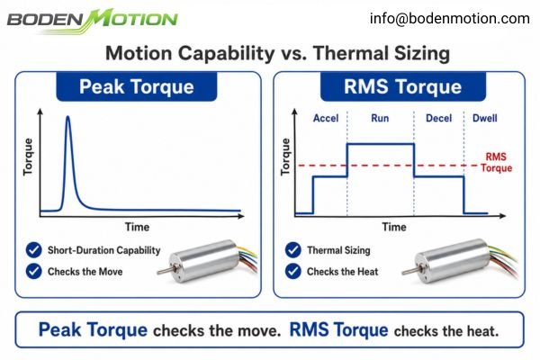
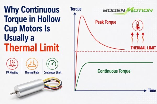
Miniature motors face a fundamental thermal challenge. They have a limited absolute surface area and low thermal mass, making it difficult to dissipate the heat generated from electrical losses (I²R). Excessive heat leads to a cascade of failures:
- Winding Insulation Failure: The enamel coating on the winding wires breaks down, leading to a short circuit.
- Magnet Demagnetization: Permanent magnets can suffer irreversible demagnetization when their allowable operating temperature is exceeded.4 This can occur well below the material's Curie temperature, depending on the magnet grade and magnetic loading.
- Bearing Failure: High temperatures degrade bearing lubricant, leading to increased friction and seizure.
To size a motor correctly, you must analyze the full duty cycle and calculate the Root Mean Square (RMS) torque5. Peak torque determines whether a transient move can be completed, while RMS torque is often more relevant to thermal sizing over the full duty cycle.
T_RMS = √[(T1²t1 + T2²t2 + … + Tn²tn) / (t1 + t2 + … + tn)]
This formula accounts for the thermal effect of acceleration, constant run, deceleration, and dwell phases.
What OEM Buyers Should Provide When Selecting Coreless Motor Size
To get the right motor, you need to provide a complete picture of the application's demands. This transforms the conversation from guesswork to a straightforward engineering calculation.
A complete motion profile—including mechanical constraints, load characteristics, dynamic requirements, and environmental factors—is necessary to correctly size a coreless motor and avoid late-stage failures.
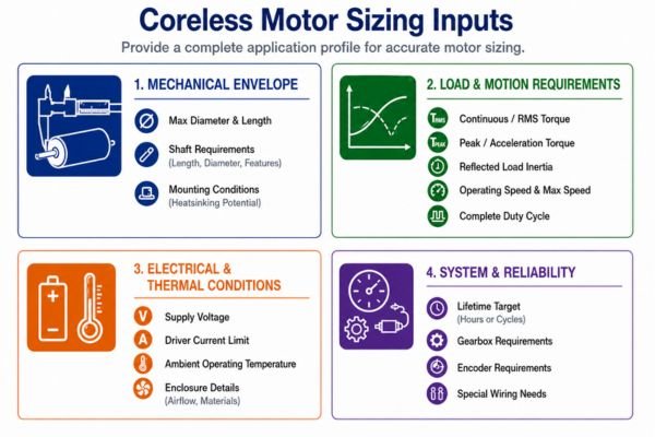
Here's a checklist of the information needed for successful motor sizing:
Mechanical Envelope
- Maximum motor diameter and length
- Shaft requirements (length, diameter, special features)
- Mounting conditions (heatsinking potential)
Load & Motion Requirements
- Continuous / RMS torque
- Peak / acceleration torque
- Reflected load inertia6
- Target operating speed and maximum speed
- A complete duty cycle description
Electrical & Thermal Conditions
- Supply voltage and driver current limit
- Ambient operating temperature
- Enclosure details (airflow, materials)
System & Reliability
- Lifetime target (hours or cycles)
- Gearbox, encoder, or special wiring needs
System-Level Observation:
Sometimes, a direct size match isn't possible. In these cases, it's worth exploring configuration adjustments. Changes in winding, target voltage, shaft design, or the addition of a planetary gearbox can often solve a sizing conflict without forcing a move to a larger motor diameter.
Coreless Motor Size Selection Guide: How to Make the Final Choice
This section translates the previous principles into a practical selection strategy. As with broader DC motor selection, the process is iterative: start with your most critical requirement, make a choice, and then validate it against all other constraints.
Sizing is a process of balancing competing requirements. You must first identify your primary constraint to guide your initial motor size selection and trade-offs.
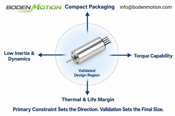
Application-Driven Selection Logic:
| If Your Primary Requirement Is... | Your Sizing Strategy Should Be... |
|---|---|
| Minimum Installation Space | Within the allowable radial envelope, evaluate if a slightly larger diameter can reduce the axial length needed to meet RMS torque and thermal requirements. |
| High Peak Torque | Where packaging allows, evaluate a larger diameter first for additional torque capability, then verify peak torque from the selected winding and operating point. |
| Fast Acceleration | Focus on a low rotor inertia and a favorable inertia ratio, which might lead to a shorter motor or a geared solution. |
| Continuous Operation | Calculate the RMS torque. Select a motor where this value is comfortably below the continuous torque rating, factoring in your actual heatsinking. |
| Precision Positioning | Aim for a favorable inertia match; ~10:1 or lower can be an initial reference for responsive systems, not a universal limit.7 |
| Long Lifetime | Avoid sizing the motor at its thermal or mechanical limits. The required margin depends on the duty cycle, temperature, and load profile. |
For an early sizing pass, I often begin with roughly a 30% torque margin when the load profile has uncertainty, then refine that margin after thermal and dynamic validation in the actual system.8
Coreless Motor Size Examples from the BODENMOTION Platform
Real-world products show how dimensions, commutation, and winding create different performance profiles. The following examples illustrate that size defines the envelope, but the configuration determines the application fit.
These models are selection references, not recommendations. They show how different design envelopes and configurations exist within a product platform.
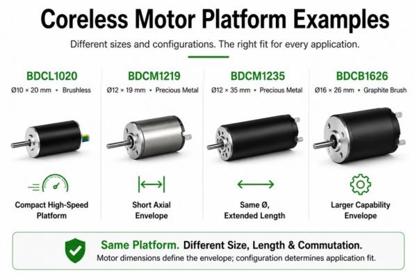
| Model | Size (mm) | Type | Selection Relevance |
|---|---|---|---|
| BDCL1020 | Ø10 × 20 | Brushless | A compact brushless example showing a small envelope can still be configured for very high-speed operation. |
| BDCM1219 | Ø12 × 19 | Brushed (Precious Metal) | A short brushed example for applications where axial packaging space is tightly constrained. |
| BDCM1235 | Ø12 × 35 | Brushed (Precious Metal) | Same diameter as the BDCM1219 but with a substantially longer axial envelope, demonstrating why length must be evaluated separately from the final electrical configuration. |
| BDCB1626 | Ø16 × 26 | Brushed (Graphite) | A larger graphite-brushed example representing a different size and commutation design space for applications requiring greater motor capability. |
These examples highlight that you cannot simply compare motors on dimensions. A brushless motor like the BDCL1020 is designed for different goals than a graphite-brushed BDCB1626. The selection must always be driven by the application's unique needs.9
Conclusion
Selecting the right coreless motor size is an engineering balance. The best choice is not simply the smallest motor that fits; it is the smallest motor that can meet the required torque, speed, dynamic response, and duty cycle with sufficient engineering margin to ensure thermal stability and long-term reliability.
If you are navigating these trade-offs for your OEM application, our engineering team can help. Feel free to reach out to us at info@bodenmotion.com to discuss your specific motion requirements.
FAQ
Is a larger coreless motor always more powerful?
A larger motor typically offers a higher potential for power and torque due to more electromagnetic volume and better thermal capacity. However, the final performance is determined by its specific winding, voltage, and commutation type.
Is a longer coreless motor better than a wider one?
There is no universal answer. A wider diameter can provide more torque and thermal design space, while a longer motor can provide additional electromagnetic design volume but may also increase rotor inertia. Its effect on torque constant, back-EMF, and maximum speed still depends on the winding, voltage, and specific motor configuration.
How much torque margin should I leave when sizing a coreless motor?
There is no universal torque-margin percentage. During early-stage sizing, a provisional margin can be useful when the load profile still contains uncertainty. I often begin around 30% as an initial engineering allowance and then refine it after thermal and dynamic validation. The final margin depends on duty cycle, temperature, transient loads, load uncertainty, and lifetime requirements.
Can a gearbox allow me to use a smaller coreless motor?
Yes, in many cases. A gearbox multiplies torque and reduces the reflected load inertia, which can allow a smaller, higher-speed motor to be used. However, this comes with trade-offs: added length, lower efficiency, potential backlash, noise, and a separate lifetime consideration for the gearbox itself.
What information should I send a motor supplier for size selection?
Provide a complete profile: maximum dimensions (diameter/length), supply voltage, operating speed, continuous (RMS) and peak torque, duty cycle, load inertia, ambient temperature, lifetime target, and any gearbox, encoder, or special shaft requirements.
"Motor Sizing Calculations", https://www.orientalmotor.com/technology/motor-sizing-calculations.html. A technical review by the National Aeronautics and Space Administration (NASA) explains that motor sizing requires consideration of multiple variables, including torque, inertia, speed, and thermal management, rather than just physical dimensions. Evidence role: expert_consensus; source type: government. Supports: motor sizing isn't just about a physical fit; it's a multi-variable engineering problem involving torque, inertia, speed, and, most importantly, heat.. Scope note: The review focuses on aerospace applications, but the principles are broadly applicable to compact device engineering. ↩
"Motion for Dummies", https://www.sjsu.edu/people/burford.furman/docs/me190/Motion_for_Dummies.pdf. Several engineering sources and servo motor manufacturers recommend a load-to-motor inertia ratio of approximately 10:1 as a general starting point for sizing, though this is not a strict stability limit and may vary depending on application specifics. Evidence role: expert_consensus; source type: education. Supports: A load-to-motor inertia ratio of around 10:1 is sometimes used as an initial servo-sizing rule of thumb.. Scope note: The 10:1 ratio is a guideline and not a universal standard; actual acceptable ratios depend on system design and requirements. ↩
"Resonant Suppression Method Based on PI control for Serial ...", https://pmc.ncbi.nlm.nih.gov/articles/PMC10358500/. Control engineering literature indicates that high load-to-motor inertia ratios can increase system overshoot and settling time, making tuning more challenging due to reduced dynamic response. Evidence role: mechanism; source type: education. Supports: a high ratio can make the system difficult to tune, often leading to overshoot and long settling times.. Scope note: The impact of inertia ratio on tuning and performance depends on other factors such as mechanical stiffness and control bandwidth. ↩
"Magnets and the Curie Temperature - Bunting Magnetics Europe", https://www.magnetapplications.com/blog/magnets-and-the-curie-temperature?hs_amp=true. Research literature and technical standards indicate that permanent magnets may experience irreversible demagnetization at temperatures significantly below their Curie temperature, with thresholds varying by magnet grade and magnetic loading. This is supported by studies on thermal stability of magnetic materials, though exact demagnetization points depend on specific application and material composition. Evidence role: mechanism; source type: research. Supports: Permanent magnets can suffer irreversible demagnetization when their allowable operating temperature is exceeded. This can occur well below the material's Curie temperature, depending on the magnet grade and magnetic loading.. Scope note: Exact demagnetization temperature depends on magnet type and application; general support only. ↩
"Motor Sizing Basics Part 3: How to Calculate Speed, Acceleration ...", https://blog.orientalmotor.com/motor-sizing-basics-part-3-acceleration-torque-and-rms-torque. Engineering textbooks and standards recommend using Root Mean Square (RMS) torque calculations to assess motor thermal loading over a duty cycle, as this method accounts for varying torque demands and their thermal effects. This approach is widely accepted in motor sizing practices, though specific calculation methods may differ by motor type and application. Evidence role: expert_consensus; source type: education. Supports: To size a motor correctly, you must analyze the full duty cycle and calculate the Root Mean Square (RMS) torque.. Scope note: Calculation details may vary by motor type and application; general support only. ↩
"[PDF] Understanding Inertia Ratio and Its Effect On Machine Performance", https://us.mitsubishielectric.com/fa/en/support/technical-support/knowledge-base/getdocument/?docid=3E26SJWH3ZZR-41-13086. Reflected load inertia is a critical parameter in motor sizing because it influences the motor's ability to accelerate and control the load; authoritative sources explain that mismatched inertia can lead to performance issues or instability. Evidence role: mechanism; source type: education. Supports: Reflected load inertia is an important parameter for motor sizing.. Scope note: The source may discuss general principles rather than specific application details. ↩
"Three Essential Factors for Servo Motor Sizing", https://www.electromate.com/news/post/three-essential-factors-for-servo-motor-sizing. A 10:1 or lower inertia ratio is commonly cited in engineering literature as a guideline for achieving responsive servo system performance, though optimal ratios may vary depending on application specifics. Evidence role: expert_consensus; source type: education. Supports: Aim for a favorable inertia match; ~10:1 or lower can be an initial reference for responsive systems, not a universal limit.. Scope note: This ratio is a general guideline and not a strict universal limit; application-specific requirements may necessitate different values. ↩
"Motor Sizing Calculations", https://www.orientalmotor.com/technology/motor-sizing-calculations.html. Engineering best practices suggest applying a torque margin of 20-30% during initial motor sizing to account for load profile uncertainties, with further refinement after system validation. Evidence role: expert_consensus; source type: education. Supports: For an early sizing pass, I often begin with roughly a 30% torque margin when the load profile has uncertainty, then refine that margin after thermal and dynamic validation in the actual system.. Scope note: The exact margin may vary based on industry standards and specific application requirements. ↩
"Selecting DC Motors - Industrial Solutions Lab - UNC Charlotte", https://isl.charlotte.edu/motors/selecting-dc-motors/. Engineering standards and guidelines, such as those published by IEEE and other technical organizations, emphasize that electric motor selection should be based on the specific requirements of the intended application, supporting the claim that application needs are paramount in motor choice. This support is general and does not address individual case studies. Evidence role: expert_consensus; source type: institution. Supports: The selection must always be driven by the application's unique needs.. Scope note: The support is general to engineering practice and not specific to the examples listed ↩