Engineers often start with motor specs like torque and speed. While these numbers are a crucial starting point, they don't fully predict performance, because a brushless DC motor's behavior in an application is strongly shaped by its driver.
The same BLDC motor can exhibit different startup, noise, and thermal characteristics depending on the driver it's paired with. This choice is a critical system-level decision.
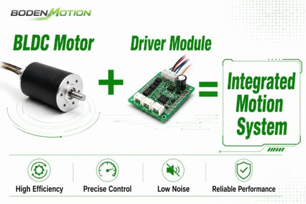
From my experience, many integration issues that surface late in development are not isolated motor problems, but rather mismatches between the motor, driver, and load1. A motor provides mechanical potential; the driver translates control signals into stable, usable motion. Understanding this relationship is key to avoiding costly redesigns.
Why Motor Specs Alone Cannot Predict Real System Behavior
A motor datasheet provides a performance baseline under ideal lab conditions. It describes the motor's potential, but it often doesn't reflect its actual output in a dynamic application where conditions are rarely static.
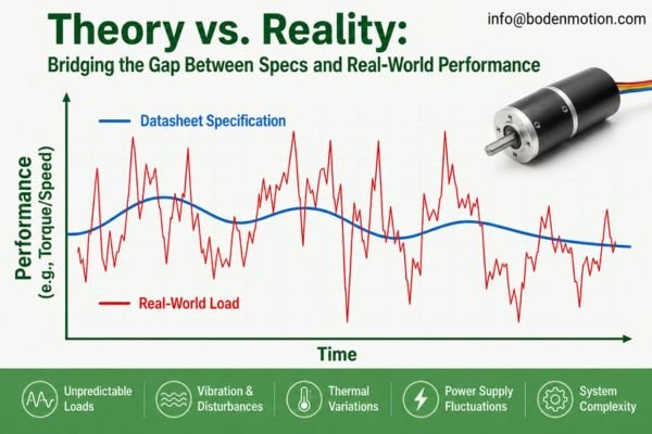
Specifications are measured at a fixed voltage with a stable load, but in a real device, performance is affected by:
- Load Inertia2: The torque required just to accelerate the physical mass.
- Startup Friction: The initial breakaway torque needed to get the system moving.
- Power Supply Fluctuations: Voltage can droop under load, affecting available torque.
- Thermal Constraints: The device enclosure's ability to dissipate heat.
Real Integration Challenge:
I worked on a medical centrifuge project where the selected motor met specs on paper but frequently failed to start. The root cause wasn't the motor itself, but the sensorless driver's inability to produce enough stable torque at zero speed to overcome the rotor's high inertia. Switching to a Hall sensor-based driver solved the problem without changing the motor.
How Driver Architecture Changes BLDC Motor Performance
The driver's architecture—whether it uses Hall sensors, sensorless algorithms, or FOC—has a major influence on the motor's startup reliability, low-speed stability, noise, and efficiency.
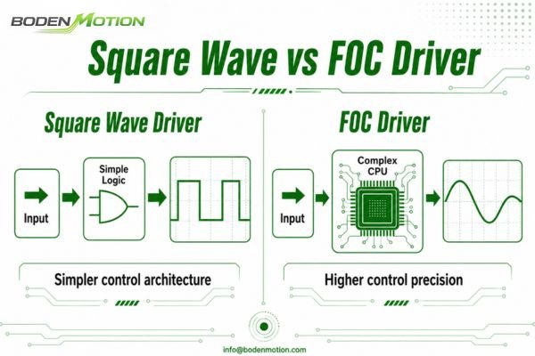
Using an unsuitable architecture is like putting the wrong fuel in an engine; you likely won't get the intended performance. A simple square wave (6-step) driver is cost-effective but can create noticeable torque ripple.3 In contrast, a Field-Oriented Control (FOC) driver uses complex algorithms to deliver smooth, sine-wave currents for quiet and efficient operation.4
| Driver Architecture | Typical Use Case | Key Trade-Offs |
|---|---|---|
| Square Wave (Hall) | General-purpose (fans, pumps) | Reliable startup; can be noisy with torque ripple. |
| Square Wave (Sensorless) | High-speed, cost-sensitive | May struggle with startup under high or variable loads. |
| FOC (Field-Oriented Control) | Precision motion (robotics, medical) | Smooth, quiet, efficient; more complex and costly. |
I've seen many teams pair a high-quality motor with a generic driver, only to be disappointed by the vibration. In many such cases, upgrading the driver to one with a better control scheme can fix the issue without needing a more expensive motor.
Why Startup Profile Is Critical in OEM Applications
Many motion system failures can occur in the first few milliseconds of operation. A sudden current surge or jerky motion can trip power supplies or damage mechanical components.
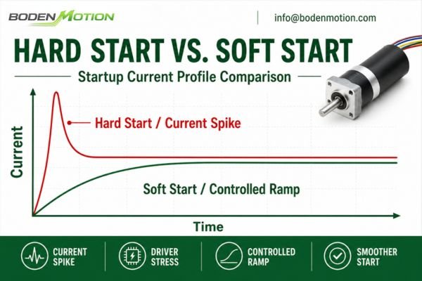
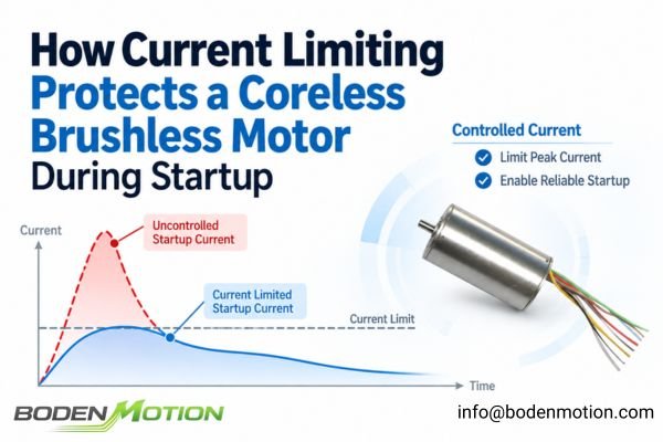
The driver's startup profile—its current limit, acceleration ramp, and initial commutation logic—is often more critical for system reliability than the motor's maximum speed rating. A poorly configured driver may simply dump current into the motor, which is especially risky in battery-powered devices.
Key startup parameters controlled by the driver include:
- Current Limiting: Prevents inrush currents that cause voltage droop.
- Acceleration Ramp: Ensures smooth acceleration to avoid mechanical shock.
- Initial Position Detection: For sensorless drivers, this is critical for a smooth start.
- Stall Protection: Shuts off power if the motor fails to start, preventing overheating.
Common OEM Mistake:
Engineers often test a motor's startup with no load, and it works perfectly. But once integrated into the device with real-world friction and inertia, it stalls.5 This is a classic symptom of a startup profile that wasn't tuned for the actual application load.
How Driver Algorithms Affect Torque Stability and Noise
If your final product has a high-pitched whine or vibrates at certain speeds, the issue is often electrical in nature, and may originate from the driver's control algorithm.
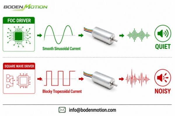
The driver's PWM frequency and commutation timing directly impact current ripple, which is a primary source of electromagnetic noise and vibration6. When the driver sends "choppy" current to the windings, it creates torque ripple—small, rapid fluctuations in torque output that cause the motor to vibrate.
| Control Method | Typical Current Waveform | Resulting Noise & Vibration |
|---|---|---|
| Square Wave (6-Step) | Blocky, trapezoidal | Higher torque ripple, noticeable commutation noise. |
| FOC (Sinusoidal) | Smooth, sine wave | Low torque ripple, quiet and smooth operation. |
For noise-sensitive applications like medical scanners or lab automation, this is not a minor detail. I have seen projects where switching from a 6-step driver to an FOC driver helped solve a persistent vibration issue7 that was previously thought to be purely mechanical.
Driver Selection and Thermal Behavior
If your motor is overheating in a sealed enclosure despite operating below its rated power, the driver settings might be a contributing factor.
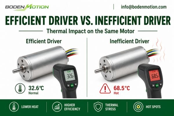
The driver influences the motor's thermal performance by controlling the quality of the current flowing through its windings. An inefficient driver or a poorly tuned one can increase the motor's copper losses (I²R) and cause it to run hotter for the same mechanical output.
A driver with high current ripple, for example, can force a higher RMS current through the windings to produce the same average torque.8 This excess current generates waste heat. When performing thermal validation, it's good practice to measure the motor temperature, driver temperature, and input power to get a full picture of the system's efficiency.
Why OEM Engineers Should Test Motor and Driver Together
Testing a motor on its own tells you only part of the story. The real insights come from testing it as an integrated system with your actual load, power supply, and enclosure. This approach helps prevent late-stage surprises.
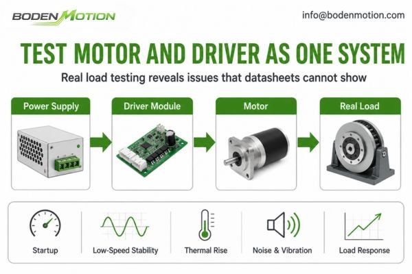
A comprehensive system test plan should validate:
- Startup performance under minimum and maximum load9.
- Low-speed stability and smoothness.
- Acceleration and deceleration response.
- Behavior during stall or overload conditions.
- Long-term thermal performance in the final product enclosure.
- Noise and vibration at various speeds and loads.
- Performance under power supply voltage fluctuations.
By testing the complete system early, you move from "will it work?" to "how well does it work in our machine?" This is where real engineering optimization begins.
Common Mistakes When Selecting BLDC Motors and Drivers
Making the right selection requires avoiding common pitfalls that I've seen derail many OEM projects. These mistakes often stem from treating the motor and driver as separate components rather than a unified system.
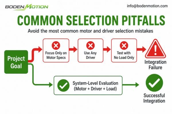
Mistake 1: Only comparing motor torque and speed
This can overlook dynamic behaviors like acceleration, settling time, and startup reliability, which are heavily influenced by the driver.
Mistake 2: Assuming any BLDC driver can work with any BLDC motor
Drivers must be well-matched to the motor's voltage, current, pole count, and sensor configuration.10 A mismatch can lead to poor performance or even damage.
Mistake 3: Testing motor performance without the real load
No-load testing is a basic check, but true performance—especially thermal behavior and control stability—only appears under real-world load conditions.
Mistake 4: Ignoring the startup profile
Many system failures occur during startup. An untuned profile may fail to start a high-inertia load or cause damaging current spikes.
Mistake 5: Treating noise as only a motor problem
Electromagnetic noise and vibration can also be caused by the driver's PWM frequency, current loop stability, or commutation algorithm.11
Conclusion
A brushless DC motor's potential is best realized through a well-matched driver. Focusing on motor specs while treating the driver as an afterthought is a common path to integration problems.
A more reliable approach is to specify and test the motor and driver as a single system tailored to your application's load, duty cycle, and control needs. If you require support matching a motor and driver solution, our engineering team is available to assist.
info@bodenmotion.com
FAQ
Is the brushless DC motor more important or the driver more important?
Both are essential, but the driver largely determines how the motor's capability is delivered. It's critical for achieving the desired real-world performance in terms of startup, noise, and efficiency.
Can one BLDC driver work with different motors?
Sometimes, if the core parameters are similar. However, for optimal performance, the driver should be tuned to the specific motor's electrical characteristics and the application's load profile.
Why does the same BLDC motor make different noise with different drivers?
Different drivers use different control algorithms and PWM frequencies. This changes the current waveform, which directly affects torque ripple and the resulting electromagnetic noise and vibration.
Why does my BLDC motor fail to start under load?
This is a classic system problem. Common causes include insufficient startup torque from the driver, an unsuitable sensorless algorithm for a high-inertia load, or the power supply's current limit being triggered.
What information should I provide when selecting a BLDC motor and driver?
To specify a system, you should provide the operating voltage, load characteristics (torque, inertia), target speed, startup conditions, duty cycle, space constraints, required control signals (e.g., PWM, direction), and any specific environmental or noise requirements.
"Load to Motor Inertia Mismatch: Unveiling The Truth", http://www.motersz.com/upload/file/tech/Inertiamatch.pdf. Engineering literature and technical guides note that integration issues in motor-driven systems often arise from mismatches between the motor, driver, and load, rather than from isolated component failures. Evidence role: expert_consensus; source type: education. Supports: many integration issues that surface late in development are not isolated motor problems, but rather mismatches between the motor, driver, and load. Scope note: The prevalence of such issues may vary by application and industry context. ↩
"Moment of inertia - Wikipedia", https://en.wikipedia.org/wiki/Moment_of_inertia. A technical source explains that load inertia is the resistance of a physical mass to changes in motion, requiring additional torque from a motor to accelerate the load, especially during startup. Evidence role: definition; source type: encyclopedia. Supports: Load Inertia: The torque required just to accelerate the physical mass.. Scope note: The explanation may not address all types of motors or specific application scenarios. ↩
"Compensation of torque ripple in high performance BLDC motor drives", https://www.sciencedirect.com/science/article/abs/pii/S0967066110001449. Engineering literature describes that square wave (6-step) motor drivers are prone to torque ripple due to abrupt commutation, supporting the claim that such drivers can create noticeable torque ripple. This support is contextual and may vary with specific motor and load conditions. Evidence role: mechanism; source type: education. Supports: A simple square wave (6-step) driver is cost-effective but can create noticeable torque ripple.. Scope note: The degree of torque ripple depends on motor design and application specifics. ↩
"Field-oriented control - Wikipedia", https://en.wikipedia.org/wiki/Field-oriented_control. Academic and engineering sources explain that Field-Oriented Control (FOC) algorithms generate sine-wave currents, resulting in smoother and quieter motor operation with improved efficiency compared to square wave drivers. This support is general and may not account for all implementation details. Evidence role: mechanism; source type: education. Supports: Field-Oriented Control (FOC) driver uses complex algorithms to deliver smooth, sine-wave currents for quiet and efficient operation.. Scope note: Actual performance depends on implementation and motor characteristics. ↩
"Induction Motor Starting Current: Load vs No- ...", https://industrialmonitordirect.com/blogs/knowledgebase/induction-motor-starting-current-on-load-vs-no-load-analysis?srsltid=AfmBOoquDYqMowUuNeZrkrEVwLavnEZa0c9s35kFjDDVpPTAwmgpjmFP. Engineering textbooks and industry reports note that testing motors under no-load conditions can lead to misleading results, as real-world loads introduce friction and inertia that may cause stalling if the startup profile is not properly tuned. This is a recognized issue in motor integration. Evidence role: expert_consensus; source type: education. Supports: Engineers often test a motor's startup with no load, and it works perfectly. But once integrated into the device with real-world friction and inertia, it stalls.. Scope note: The support is based on general engineering practice and may not quantify the exact prevalence of this mistake. ↩
"Noise in Electric Motors: A Comprehensive Review - MDPI", https://www.mdpi.com/1996-1073/16/14/5311. Technical literature on electric motor control indicates that current ripple, influenced by PWM frequency and commutation timing, is a significant contributor to electromagnetic noise and vibration in motors. This is supported by studies analyzing the relationship between current waveform quality and acoustic/electromagnetic emissions. However, the degree of impact may vary depending on motor type and application context. Evidence role: mechanism; source type: paper. Supports: The driver's PWM frequency and commutation timing directly impact current ripple, which is a primary source of electromagnetic noise and vibration.. Scope note: The support is contextual and may not apply equally to all motor designs or operating conditions. ↩
"Field Oriented Control-Based Reduction of the Vibration and Power ...", https://www.mdpi.com/1996-1073/13/15/3907. Case studies and technical reports in the field of motor control have documented instances where transitioning from 6-step (square wave) to FOC (sinusoidal) control methods resulted in reduced vibration and noise, particularly in precision and noise-sensitive applications. While these findings support the claim, results may depend on specific system configurations and implementation quality. Evidence role: case_reference; source type: research. Supports: Switching from a 6-step driver to an FOC driver helped solve a persistent vibration issue that was previously thought to be purely mechanical.. Scope note: The evidence is based on documented cases and may not universally apply to all projects or environments. ↩
"PWM power stage: Current ripple & Motor chokes - maxon Support", https://support.maxongroup.com/hc/en-us/articles/360005046213-PWM-power-stage-Current-ripple-Motor-chokes. Research literature on motor control demonstrates that increased current ripple in motor drivers leads to higher RMS current, which in turn raises copper losses and heat generation for a given torque output. Evidence role: mechanism; source type: paper. Supports: A driver with high current ripple, for example, can force a higher RMS current through the windings to produce the same average torque.. Scope note: Most studies focus on specific motor types and driver architectures; results may vary for different systems. ↩
"Load testing of motors: Common methods, procedures - EASA", https://easa.com/resources/resource-library/load-testing-of-motors-common-methods-procedures-1. Industry standards such as those from IEEE and engineering best practices recommend evaluating startup performance under both minimum and maximum load conditions to ensure reliable operation and identify potential failure modes. This support is contextual and may vary depending on the specific system type. Evidence role: expert_consensus; source type: institution. Supports: A comprehensive system test plan should validate startup performance under minimum and maximum load.. Scope note: Support may depend on the type of system or motor being tested; not all standards require both minimum and maximum load testing. ↩
"Brushless DC (BLDC) Motor Drivers - STMicroelectronics", https://www.st.com/en/motor-drivers/brushless-dc-motor-drivers.html. Technical sources confirm that BLDC motor drivers must be matched to the motor's voltage, current, pole count, and sensor configuration to ensure proper operation and avoid potential damage; this is a general engineering consensus, though specific requirements may vary by application. Evidence role: expert_consensus; source type: education. Supports: Drivers must be well-matched to the motor's voltage, current, pole count, and sensor configuration.. Scope note: Application-specific requirements may differ; general support only. ↩
"Common Causes of BLDC Motor Noise and How to Reduce It", https://www.leanmotor.com/common-causes-of-bldc-motor-noise-and-how-to-reduce-it.html. Research literature indicates that electromagnetic noise and vibration in BLDC systems can be influenced by driver parameters such as PWM frequency, current loop stability, and commutation algorithm; however, the degree of impact depends on system design and operating conditions. Evidence role: mechanism; source type: paper. Supports: Electromagnetic noise and vibration can also be caused by the driver's PWM frequency, current loop stability, or commutation algorithm.. Scope note: The influence varies with system design and operating conditions; not all systems are equally affected. ↩