Your pick-and-place system may feel sluggish, even with a high-RPM motor. The issue is often not maximum speed, but the time lost during acceleration, deceleration, and settling under the application's real-world load.
High-speed coreless motors can improve pick-and-place systems by leveraging their low rotor inertia for faster acceleration and deceleration, which can lead to reduced cycle times and more consistent positioning under the right system conditions.
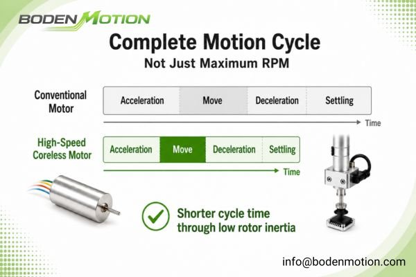
In my experience as a motor engineer, the conversation about pick-and-place performance needs to shift. We must move beyond simply asking "How fast can it spin?" to a more critical question: "How quickly and consistently can the motor execute a complete motion cycle under the system's actual load?" This system-level view reveals the practical advantages of a coreless motor's architecture for dynamic applications1. This article breaks down the engineering principles behind this potential performance gain2.
What a High-Speed Coreless Motor Means in Pick-and-Place Systems
Your system needs to be fast, but "fast" is a vague term in automation. A motor with a high no-load RPM can still result in a slow machine if it cannot respond quickly to commands.
In pick-and-place systems, "high-speed" should mean fast motion-cycle response, not only high no-load RPM. Low rotor inertia helps improve acceleration, deceleration, and settling behavior in repeated short-stroke motion.Heavy loads, high continuous torque, or shock conditions still require full system review.
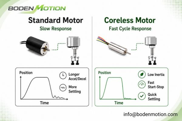
The term "high-speed" here describes the motor's ability to complete a motion profile quickly. The coreless design, which lacks a heavy iron core in the rotor, is the key. For a pick-and-place system executing thousands of short, repetitive start-stop movements, this can be a practical advantage, allowing the control system to manage the actuator with greater agility.3
Why Low Rotor Inertia Improves Acceleration and Cycle Time
Your cycle time is too long, and simply increasing the motor's maximum RPM doesn't help. The true bottleneck is often the time spent starting and stopping during each move.
Low rotor inertia can directly improve cycle time by reducing the torque—and therefore the time—required for the acceleration and deceleration phases of the motion profile.
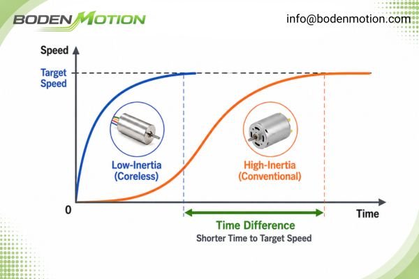
In many short-stroke applications, the majority of the cycle time is consumed by acceleration and deceleration. The physics are governed by the equation Torque (τ) = Inertia (I) × Angular Acceleration (α)4. If the inertia (I) is low, the motor needs less torque to achieve the same acceleration. This provides several system-level benefits:
- Faster Acceleration: For a given driver current limit, lower inertia allows for higher acceleration.
- Reduced Cycle Time: Shaving milliseconds off every acceleration and deceleration phase can increase throughput.
- Lower Peak Current: Since less torque is needed to overcome rotor inertia, peak current draw can be lower, reducing electrical stress and heat.
The following simplified example is for concept illustration only. Actual results depend on payload, reflected inertia, stroke length, driver current, feedback resolution, and mechanical stiffness.
| Motion Cycle Phase | High-Inertia Motor (Example) | Low-Inertia Coreless Motor (Example) | Impact in this Example |
|---|---|---|---|
| Acceleration Time | 50 ms | 15 ms | Faster start |
| Constant Speed Travel | 20 ms | 20 ms | Same |
| Deceleration Time | 50 ms | 15 ms | Faster stop |
| Settling Time | 25 ms | 5 ms | Reduced overshoot |
| Total Motion Time | 145 ms | 55 ms | Shorter cycle in this simplified example |
This example shows why acceleration and settling time can dominate short-stroke motion cycles.
How Coreless Motors Support Positioning Speed and Repeatability
Your actuator moves fast, but it either overshoots the target or takes too long to settle. This harms throughput and placement accuracy.
The low inertia of coreless motors allows the control loop to command and achieve precise stops with potentially less overshoot and faster settling times, which can enhance positioning repeatability.
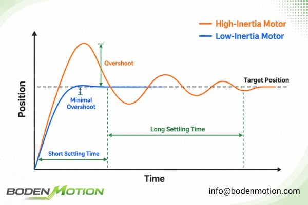
A coreless motor's lightweight rotor stores very little kinetic energy, giving it less tendency to "coast" past a target.5 This makes the control task easier, which can result in:
- Faster Settling Time: The motor may stop and stabilize at the target position more quickly.
- Improved Positioning Accuracy: Reduced overshoot can mean the final position is more consistent.
- Less Aggressive Control Tuning: The PID controller may not need to be tuned as aggressively to manage the motor's momentum.
Real Integration Challenge: The benefits of a low-inertia motor can be compromised by a mechanically "soft" system. Backlash in gears or a flexible belt drive will prevent the motor's precision from translating to the end-effector. High mechanical stiffness is crucial to capitalize on the motor's responsiveness.6
Why Payload and Mechanical Load Define the Motor Requirement
You've selected a responsive coreless motor, but it struggles once integrated. The problem is often not the motor itself, but the unaccounted-for system load.
The motor selection must be based on the total system inertia—including payload and mechanics—as this "reflected inertia" can be significantly larger than the motor's own rotor inertia.
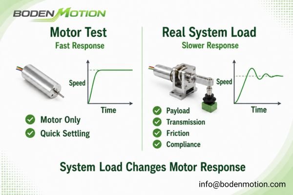
A coreless motor has low rotor inertia, but it is connected to a mechanical system. The total inertia the motor must control is its own rotor inertia plus the reflected inertia of the entire moving assembly. Some motion-control designs use the inertia ratio (load inertia / motor inertia) as a reference7, but the acceptable range depends heavily on the acceleration target, mechanical stiffness, control bandwidth, and driver capability. A high inertia mismatch can diminish the benefits of a coreless design and challenge the control system.
The Critical Role of Transmission Design
The motor’s low-inertia advantage must be evaluated together with the transmission method. Mechanical components like gearboxes, belts, and ball screws significantly impact the system's dynamic performance. A gearbox can increase output torque but also increases the reflected inertia by the square of the gear ratio. A flexible belt can introduce compliance and vibration, while a ball screw may have its own inertia and friction characteristics. These factors—reflected inertia, backlash, compliance, and stiffness—must be considered as part of the total system to ensure the motor's responsiveness translates to the final payload.
How High-Speed Coreless Motors Help Compact Automation Design
You are designing a compact automation module, but bulky motors are forcing design compromises, making the equipment larger and heavier than desired.
High-speed coreless motors can support compact design by offering a high power-to-weight ratio, enabling smaller, lighter actuators that still provide rapid dynamic response.
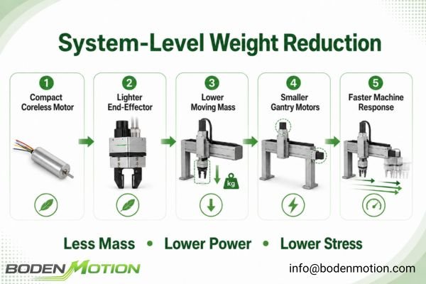
This creates a positive feedback loop in system design. Using a lightweight coreless motor in a pick-and-place head reduces the mass at the end of the gantry or robotic arm8. This, in turn, reduces the load that the main X, Y, and Z axes must move. As a result, the primary gantry motors can potentially be smaller, further reducing overall system mass, power consumption, and mechanical stress on structural components. This system-wide weight reduction can be a key factor in achieving faster overall machine response.
What OEM Buyers Should Confirm Before Choosing a High-Speed Coreless Motor Supplier for Automation
You need more than a catalog; you need a supplier who understands the system-level challenges of pick-and-place automation.
A capable supplier should not only provide motors but also offer technical support for integration, including customization and validation discussions.
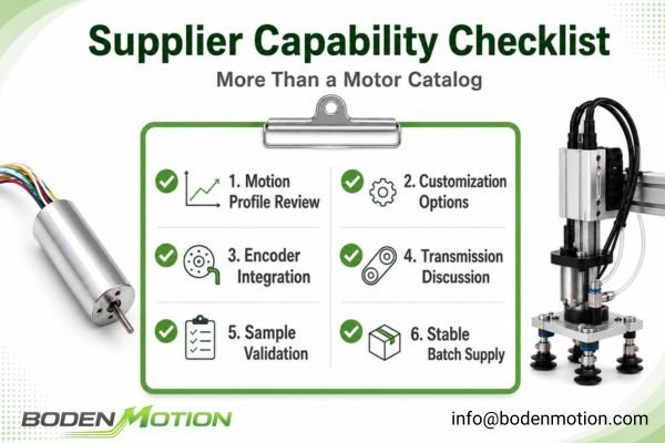
When evaluating suppliers, OEM buyers should confirm their capabilities in key areas that support successful integration:
- Application Engineering9: Can they discuss your motion profile, load, and inertia calculations to help with motor sizing?
- Customization Options: Do they offer customization for shafts (length, D-cuts), lead wires, and connectors to match your mechanical and electrical interface?
- Feedback Integration: Can they provide or recommend compatible encoders and support their integration to meet your positioning requirements?
- Transmission Discussion: Are their engineers able to discuss the impact of gearboxes, belts, or screw drives on motor performance?
- Sample Testing & Validation: Do they support a clear sample testing process for you to validate performance in your prototype?
- Stable Batch Supply10: Can they demonstrate a track record of stable quality and reliable delivery for volume production?
Common Mistakes When Selecting Motors for Pick-and-Place Systems
Your pick-and-place prototype is not meeting performance targets despite using a "high-performance" motor. As with broader DC motor selection, the problem is often not a single specification but how the motor is matched to the complete motion system.
The most frequent errors involve focusing on a single specification like RPM while ignoring critical system-level factors such as total inertia, duty cycle, and thermal management.
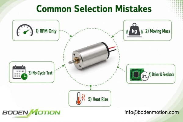
- Focusing only on maximum RPM: In short-stroke pick-and-place, acceleration capability is often more critical for reducing cycle time.
- Ignoring the total moving mass: The motor must move the payload plus the gripper, brackets, and transmission components.
- Testing without the real motion cycle: The motor must be tested under the actual start-stop duty cycle to evaluate thermal behavior and response.
- Underestimating driver and feedback needs: An undersized driver, low-resolution encoder, or poorly tuned control loop will prevent you from realizing the motor's full potential.
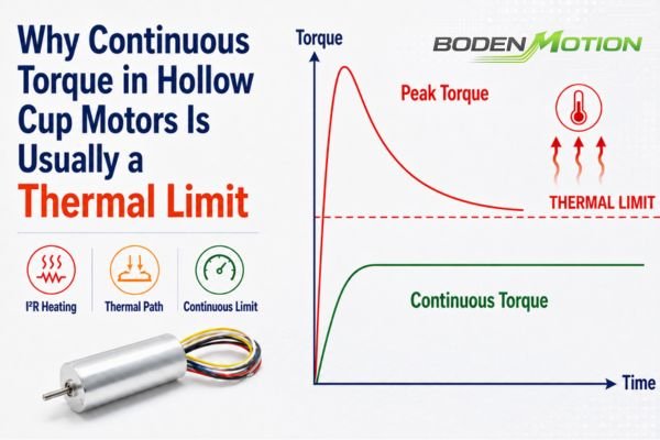
- Ignoring heat from repeated operation: The current spikes during frequent acceleration generate significant heat (I²R losses).
Prototype Validation: The Critical Final Step
Datasheet values and simulations provide a starting point, but physical testing is essential. OEM engineers should validate the selected motor in the actual prototype under the real motion profile. Key validation checks include measuring acceleration time, stopping behavior, settling time, peak driver current during the cycle, and motor temperature rise after extended operation. It's also crucial to verify positioning repeatability and noise levels after thousands of cycles to ensure the system meets long-term performance and reliability targets.
Conclusion: Match the Motor to the Real Operating Point
Success with coreless motors in pick-and-place systems depends on more than raw RPM. The key is to match low rotor inertia and fast dynamic response with the complete operating condition, including payload, transmission design, control strategy, duty cycle, and thermal limits. For OEM engineers, this means evaluating the motor as part of the full motion system, not as an isolated datasheet component.
If you are developing a compact pick-and-place module, BODENMOTION can support motor selection based on your real application data. Please send us your voltage, stroke length, payload, target cycle time, motor size limits, driver type, and duty cycle for technical review. Contact us at info@bodenmotion.com.
FAQ: High-Speed Coreless Motors in Pick-and-Place Systems
Q1: Why are high-speed coreless motors used in pick-and-place systems?
Their primary advantage is low rotor inertia, which allows for rapid acceleration and deceleration. This can reduce overall cycle time in the short, repetitive motions typical of pick-and-place tasks.
Q2: Is maximum RPM the most important factor for pick-and-place performance?
Not usually. For short-stroke movements, factors like acceleration, deceleration, and settling time are often more critical for reducing cycle time and improving throughput than the motor's maximum no-load speed.
Q3: How does low rotor inertia improve automation performance?
Low inertia means less torque is required to start and stop the motor's own rotor. This allows more of the motor's available torque to be used for accelerating the actual load, enabling a faster system response.
Q4: What information should OEM buyers prepare before selecting a coreless motor?
To get an accurate recommendation, prepare key parameters: required voltage, target cycle time, payload weight and dimensions, stroke length, total moving mass, driver specifications, required precision, and any physical or environmental constraints.
Q5: When might a coreless motor NOT be the best choice for pick-and-place?
A coreless motor may not be ideal for applications with very heavy payloads, high continuous torque requirements (e.g., holding a heavy load against gravity without a brake), or significant external shock and vibration. In such cases, or for very low-cost systems where dynamic performance is less critical, other motor types like a geared or stepper motor might be a more suitable engineering choice.
PDF source: Sensorless Control of Low Inductance Coreless AFPM Machines. Available from University of Kentucky SPARK Lab. A review of coreless motor technology indicates that their architecture offers reduced inertia and improved acceleration, which can be advantageous in dynamic applications such as robotics and precision instruments. ↩
"Why Do Coreless Brushed DC Motors Respond Faster?", https://bodenmotion.com/why-coreless-brushed-dc-motors-respond-faster/. Educational resources and technical literature describe the engineering principles of coreless motors, including their reduced mass, absence of iron core, and resulting lower inertia, which contribute to improved performance in rapid motion cycles. These principles are widely recognized in motor design textbooks and university courses. Evidence role: definition; source type: education. Supports: This article breaks down the engineering principles behind this potential performance gain.. Scope note: The explanation is general and may not address all specific engineering scenarios. ↩
"How Coreless Motors Improve Precision Control | BODENMOTION", https://bodenmotion.com/coreless-motors-precision-motion-control/. Research on pick-and-place automation systems indicates that low-inertia actuators, such as coreless motors, enable more agile and responsive control during rapid, repetitive movements. Evidence role: mechanism; source type: research. Supports: allowing the control system to manage the actuator with greater agility.. Scope note: The evidence may focus on general actuator performance in automation rather than specifically on coreless motors. ↩
"Refresher on the Basics of Angular Acceleration and Moment of Inertia", https://www.rw-america.com/refresher-on-the-basics-of-angular-acceleration-and-moment-of-inertia/. This equation is a fundamental principle of rotational dynamics, as described in classical physics literature, and relates torque, moment of inertia, and angular acceleration. Evidence role: definition; source type: education. Supports: The physics are governed by the equation `Torque (τ) = Inertia (I) × Angular Acceleration (α)`.. ↩
"How Coreless Motors Improve Precision Control | BODENMOTION", https://bodenmotion.com/coreless-motors-precision-motion-control/. A technical review of coreless DC motors explains that their rotors are lighter and have lower inertia, resulting in reduced kinetic energy and less tendency to overshoot or 'coast' when stopping, which supports the claim about easier control. Evidence role: mechanism; source type: education. Supports: A coreless motor's lightweight rotor stores very little kinetic energy, giving it less tendency to "coast" past a target.. Scope note: Most sources discuss this in the context of small precision motors; applicability to larger or non-standard designs may vary. ↩
"Precision in Motion Control: Overcoming Challenges to Achieve ...", https://www.automate.org/motion-control/industry-insights/developing-precision-motion-control-systems. Engineering literature on precision motion systems emphasizes that high mechanical stiffness is necessary to transmit motor responsiveness effectively, supporting the claim that stiffness is crucial for performance. Evidence role: expert_consensus; source type: education. Supports: High mechanical stiffness is crucial to capitalize on the motor's responsiveness.. Scope note: The importance of stiffness is generally accepted in precision applications, but specific requirements may depend on system design. ↩
"Motor Sizing Basics Part 2: How to Calculate Load Inertia", https://blog.orientalmotor.com/motor-sizing-basics-part-2-load-inertia. Technical literature and engineering textbooks describe the inertia ratio as a common metric for sizing motors in motion control applications, where it is used to assess system stability and performance. Evidence role: general_support; source type: education. Supports: Some motion-control designs use the inertia ratio (load inertia / motor inertia) as a reference.. Scope note: The optimal inertia ratio may vary depending on specific application requirements and control strategies. ↩
"Comprehensive shape optimization based on reliability for a robot arm", https://www.sciencedirect.com/science/article/pii/S1110016826003522. A technical source explains that reducing the mass at the end of a robotic arm or gantry decreases the inertia, which can improve acceleration and reduce the required force from the actuators. Evidence role: mechanism; source type: education. Supports: Using a lightweight coreless motor in a pick-and-place head reduces the mass at the end of the gantry or robotic arm.. Scope note: The specific impact depends on the system's design and application context. ↩
"Benefit From Early Engagement with a Motor Design Engineer", https://islproducts.com/design-note/benefits-of-early-engagement-with-an-applications-engineer-dc-motors-gear-motors/?srsltid=AfmBOooXwPTVAv31eMo0aw4FecXd4PSqWOjBZ6DOFlnyYhwaWNBcnH4v. Industry guidelines indicate that supplier application engineering support is critical for accurate motor sizing, as it ensures proper consideration of motion profiles, load, and inertia calculations. Evidence role: expert_consensus; source type: education. Supports: OEM buyers should confirm that suppliers can discuss motion profile, load, and inertia calculations to help with motor sizing.. Scope note: This support is generally recommended in engineering best practices but may vary by application complexity. ↩
"[PDF] Common Problems & Collaborative Solutions: OEM-Supplier ...", https://highroad.wisc.edu/wp-content/uploads/sites/2056/2020/05/2000-Common-Problems-Collaborative-Solutions-OEM-Supplier-Relationships-and-the-Wisconsin-Manufacturing-Partnerships-Supplier-Training-Consortium.pdf. Research on supplier selection emphasizes that a proven track record of stable quality and reliable delivery is essential for successful OEM volume production. Evidence role: expert_consensus; source type: research. Supports: OEM buyers should confirm that suppliers can demonstrate a track record of stable quality and reliable delivery for volume production.. Scope note: While widely recognized in supply chain management literature, specific requirements may differ by industry sector. ↩