A coreless motor winding is more than an electrical conductor arrangement; it is a key electromechanical structure whose geometry and manufacturing process influence resistance, torque production, thermal behavior, mechanical stability, and production consistency.
The coreless motor winding process directly influences electromagnetic performance, copper utilization, thermal behavior, dimensional stability, and manufacturing consistency. In brushed coreless motors, where the winding rotates with the armature, winding design also directly affects rotor inertia and dynamic balance.
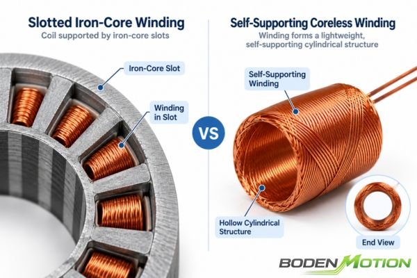
In a conventional slotted iron-core motor, copper conductors are placed inside defined slots. In a coreless motor, the winding instead forms a lightweight, self-supporting cylindrical structure, making conductor placement, forming accuracy, bonding, resistance, end-turn geometry, and thermal behavior especially important. There is no universally "best" winding method; the appropriate architecture depends on the motor topology and required operating conditions. One important distinction is that the winding rotates as part of the armature in a brushed coreless DC motor, while in a brushless coreless / slotless BLDC motor, the winding typically remains stationary as part of the stator, which changes how winding design affects mechanical factors such as rotor inertia and balance.
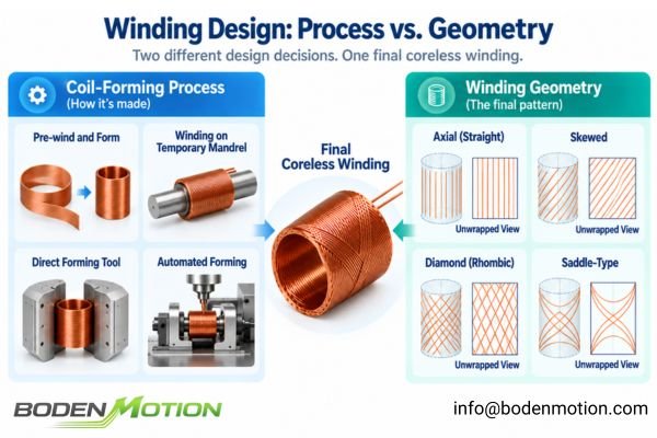
Coil-Forming Process vs Winding Geometry: Two Different Design Decisions
Engineers often use the term "winding method" to describe two different things. Separating them is the first step toward a clearer understanding.
The physical manufacturing process and the final conductor geometry are two distinct, though related, engineering decisions that define a coreless winding.
In OEM motor projects, confusion between these two concepts can lead to unclear specifications and unnecessary miscommunication between the customer and motor supplier.
Coil-Forming Process
This answers the question: How is the physical, cylindrical coil manufactured? It describes the manufacturing route.
- Winding wire into an intermediate shape, then forming it.
- Winding directly onto a temporary, removable mandrel.
- Using a dedicated tool for direct, near-final-shape forming.
- Leveraging highly automated, integrated winding and forming processes.
Winding Geometry
This answers the question: How is the conductor distributed around the cylindrical winding structure? It describes the final path of the wire. While terminology varies between manufacturers, common descriptions include straight/axial, skewed, diamond/rhombic, and saddle-type arrangements.
| Design Dimension | Main Question | Main Engineering Impact |
|---|---|---|
| Coil-forming process | How is the coil physically produced? | Tolerance, automation, repeatability, minimum size |
| Winding geometry | How is conductor distributed around the cylindrical structure? | Active copper, end turns, resistance, torque distribution |
| Wire specification | What conductor is used? | Resistance, current density, thermal behavior |
| Final forming/bonding | How is the winding stabilized? | Mechanical strength, dimensional stability, repeatability |
Wound-and-Formed vs One-Step Forming: How the Manufacturing Process Changes
The route taken to create the coil has a significant impact on consistency, flexibility, and cost, especially at scale.
A more automated process is not automatically a better electromagnetic design; manufacturing process and motor performance must be optimized together.
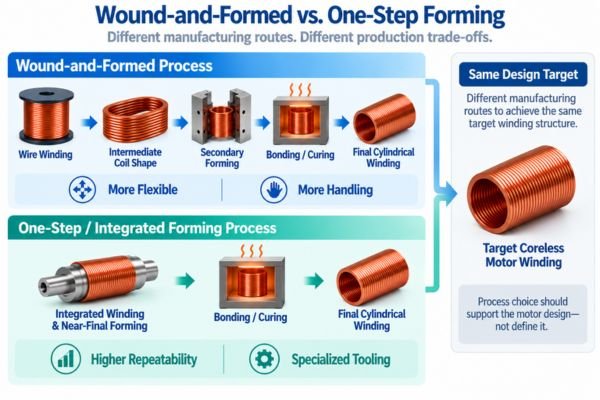
Wound-and-Formed Process
This is a more traditional, multi-stage approach. The general sequence is:
Wire winding → Intermediate coil shape → Forming → Bonding/curing → Final cylindrical winding structure
- Potential advantages: Can be more flexible for design changes, suitable for a wide range of geometries, and may use more mature tooling.
- Potential challenges: Multiple handling and forming steps can introduce process variation, risk conductor displacement, and make tight dimensional control more difficult.
One-Step / Integrated Forming Process
Here, the winding is created much closer to its final geometry during the initial winding operation, reducing secondary steps.
- Potential advantages: Fewer secondary operations can lead to better repeatability and dimensional consistency, especially in high-volume, automated production.
- Potential challenges: Tooling is often more specialized and complex. Small design changes might require significant tooling or programming adjustments.
The choice is often an economic and quality trade-off. For high-volume, high-consistency applications, the investment in a sophisticated, integrated process can be justified by repeatability and production efficiency. For customized, lower-volume windings, a more flexible, multi-stage process may be more practical.
Common Coreless Winding Geometries and Their Engineering Trade-Offs
The conductor path determines how the winding interacts with the magnetic field and how much conductor is required to achieve the target electromagnetic design. Each geometry therefore presents a different set of trade-offs.
No single winding geometry is inherently superior; the appropriate choice depends on the required balance of torque production, conductor length, resistance, packaging, and manufacturability.
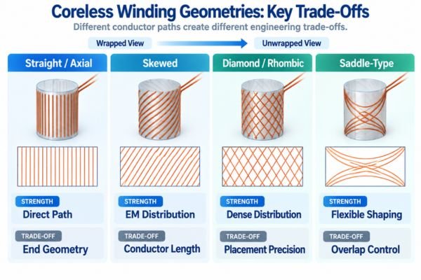
Terminology is not completely standardized between manufacturers. Terms such as diamond, rhombic, concentric, skewed, and saddle-type may sometimes overlap or describe closely related forming concepts. For engineering evaluation, the actual conductor path and resulting electromagnetic and manufacturing effects matter more than the label itself.
Straight / Axial-Oriented Winding
The conductors have a relatively direct path along the active length. While geometrically simpler, achieving uniform conductor distribution and managing end-turn geometry remain important design considerations.
Skewed Winding
Conductors are arranged at an angle relative to the motor axis1. Depending on winding pitch, pole configuration, and motor topology, a skewed arrangement can influence torque smoothness and conductor distribution. It may also increase total conductor length depending on the end-turn and winding geometry.
Diamond / Rhombic-Type Winding
This geometry uses crossing conductor paths to create a dense, interlocking pattern. It can support dense circumferential conductor distribution and effective use of the available winding volume, but the actual copper utilization depends on the complete geometry, wire specification, and forming process. Precise wire placement and process control are important.
Saddle-Type Winding
This term is commonly used for shaped coil sections or conductor paths arranged around a cylindrical structure. Depending on the manufacturer's terminology and forming method, saddle-type concepts may overlap with other winding descriptions. Their engineering value should therefore be assessed through conductor placement, end-turn length, overlap, balance, and manufacturability rather than terminology alone.
| Winding Geometry | Potential Strength | Main Trade-Off to Evaluate |
|---|---|---|
| Straight/Axial | Relatively direct conductor path | Copper distribution / end geometry |
| Skewed | Can influence electromagnetic distribution and torque smoothness | Conductor length / process complexity |
| Diamond/Rhombic | Can support dense circumferential distribution | Crossing and forming precision |
| Saddle-Type | Flexible shaped-coil arrangement | Geometry definition / overlap / assembly control |
How Winding Geometry Influences Copper Utilization, Resistance, and Torque
Not every millimeter of copper wire in a winding contributes equally to useful torque. This is a critical concept in coreless motor design.
The objective is not maximum copper quantity, but effective copper placement within the available motor volume.
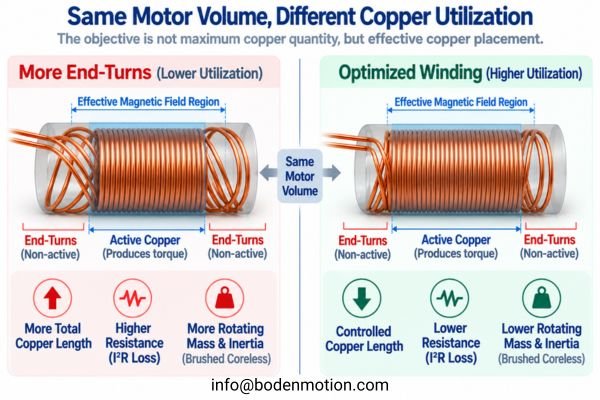
We can separate the winding into two functional parts:
- Active Copper: The portion of the conductors positioned within the effective magnetic field, where current and magnetic flux interact to produce useful torque.
- End-Turn / Transition Copper: The conductor required to complete the electrical path between active sections. It contributes relatively little to useful torque but still adds conductor length, resistance, copper mass, and thermal load.
A winding geometry with longer or bulkier end turns generally requires more total wire length. Under otherwise comparable conditions, this can increase winding resistance (R) and resistive heating (I²R loss) for a given current.
The design goal is therefore to achieve the required torque constant with efficient active-copper utilization, controlled conductor length, acceptable resistance, and sufficient thermal margin. In brushed coreless motors with rotating windings, unnecessary end-turn mass also directly increases rotating mass and rotor inertia.
Why Winding Design and Process Affect Inertia, Heat, Balance, and High-Speed Behavior
Winding design is not only an electrical consideration. Geometry, forming accuracy, bonding, and motor topology can also influence the motor's mechanical and thermal behavior.
The mechanical impact of winding design depends strongly on whether the winding rotates with the armature or remains stationary as part of a slotless stator.
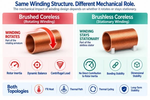
Rotor Inertia in Brushed Coreless Motors
For brushed coreless motors, the self-supporting winding is part of the rotating armature. Unnecessary copper in the end turns or excess bonding material therefore adds directly to rotating mass and inertia.
This affects how quickly the motor can accelerate, decelerate, or reverse direction. In a brushless coreless motor, by contrast, the winding remains stationary and its mass does not directly contribute to rotor inertia.
Thermal Behavior
Thermal behavior is important in both topologies. Heat generated in the winding through I²R losses must be transferred away through the available thermal paths.
Copper packing density, conductor size, bonding material, contact with surrounding structures, housing design, and operating duty cycle all influence winding temperature. A dense winding can provide efficient copper utilization, but thermal performance still depends on how effectively heat can leave the winding and reach the surrounding structure.
Rotor Balance in Brushed Coreless Motors
At high speeds, asymmetries in the mass distribution of a rotating winding can contribute to vibration, audible noise, bearing loading, and reduced mechanical life2.
Uneven conductor placement, inconsistent forming, non-uniform adhesive application, or dimensional variation can therefore affect dynamic balance in brushed coreless motors with rotating windings.
Mechanical Stability
For a rotating brushed winding, the structure must withstand centrifugal loading at high RPM as well as repeated acceleration, deceleration, and thermal cycling.
For a stationary brushless winding, mechanical stability is more closely related to dimensional integrity, bonding retention, thermal cycling, and resistance to vibration or shock from the surrounding system.
In both cases, winding and bonding quality contribute to long-term dimensional and electrical stability.
How Diameter and Production Volume Influence Winding Process Selection
A process that is suitable for a 16 mm motor may be impractical for a 6 mm motor or for a production run of millions of units.
Winding process selection is context-dependent and strongly influenced by motor size, required performance, and production scale.
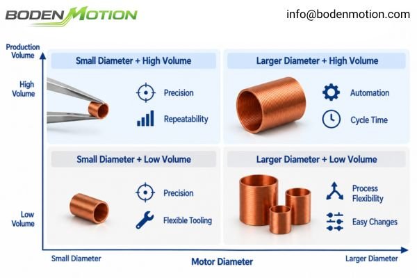
- For very small diameter motors, the priority shifts toward placement precision, wire handling, forming accuracy, and dimensional consistency. Small errors have a proportionally larger effect on the available winding volume and final geometry.
- For high-RPM applications, the requirements depend on motor topology. Rotating windings place greater emphasis on balance and mechanical retention, while stationary windings place more emphasis on dimensional stability, thermal behavior, and resistance to system vibration.
- For high-volume production, the focus is on automation, repeatability, cycle time, and process capability to maintain consistent output across large production lots.
- For lower-volume or customized motors, process flexibility becomes more important. Tooling and winding programs that can accommodate design changes may be more economical for development and smaller production batches.
| Design Constraint | Winding Process Priority |
|---|---|
| Very small diameter | Placement precision + forming stability |
| High RPM with rotating winding | Balance + mechanical retention |
| High torque density | Effective copper utilization |
| Low inertia with rotating winding | Minimize unnecessary rotating copper mass |
| Low resistance target | Conductor length + wire specification |
| Large production volume | Automation + repeatability |
| Multiple custom windings | Process flexibility |
How Engineers Should Select a Coreless Motor Winding Configuration
This brings us to the final practical question: How should an OEM engineer use this information?
OEM buyers should not begin by requesting a specific winding label such as "diamond winding." They should first define the required motor performance and allow the manufacturer to optimize the winding architecture around the actual operating conditions.
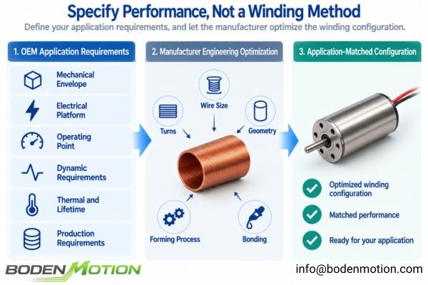
The winding configuration should be selected from the required operating point, not the other way around.
In practice, the same mechanical motor platform can use different winding configurations to match different electrical systems3. For example, the BDCM1331 coreless brushed DC motor is available with 3V, 6V, 12V, and 24V winding versions, with corresponding differences in winding resistance and torque constant. This illustrates why winding selection should begin with the electrical platform and target operating point rather than with a winding-geometry name.
Here is the information needed to start a productive OEM discussion:
- Mechanical Envelope: Motor diameter, maximum length, shaft requirements, and weight limitations.
- Electrical Platform: Rated voltage, operating voltage range, and driver current limits.
- Torque-Speed Operating Point: Target speed, continuous torque, and peak torque requirements.
- Dynamic Requirements: Required acceleration, start-stop frequency, and load inertia.
- Thermal and Lifetime Requirements: Duty cycle, ambient temperature, allowable thermal limits, and expected lifetime.
- Production Requirements: Sample quantities, forecast volume, and any special consistency or traceability requirements.
With these inputs, the motor manufacturer can evaluate winding turns, conductor size, coil geometry, forming process, and bonding approach around the actual system requirements.
Conclusion
A coreless motor winding is the result of multiple interconnected engineering decisions, including conductor geometry, wire specification, forming process, and bonding method. These choices must be balanced against electromagnetic performance, copper utilization, resistance, thermal margin, mechanical stability, and manufacturing consistency. Their mechanical consequences also depend on motor topology: a rotating winding in a brushed coreless motor has different inertia and balance considerations from a stationary winding in a slotless brushless motor.
For OEM engineers, the more useful question is not “Which winding method is best?” but “Which winding architecture best supports the required diameter, voltage, speed, torque, duty cycle, dynamic response, and production conditions?” Providing these system-level requirements gives the motor manufacturer the information needed to optimize the winding and motor configuration around the real application. For OEM motor evaluation or customization, you can contact the BODENMOTION engineering team at info@bodenmotion.com.
FAQ
Q1: What are the main coreless motor winding methods?
Coreless motor windings differ in both their manufacturing process—such as wound-and-formed or more integrated forming methods—and their final conductor geometry, such as straight/axial, skewed, or diamond/rhombic arrangements. These are separate but related design dimensions, and terminology can vary between manufacturers.
Q2: Is diamond winding better than straight winding?
Not universally. Different geometries create different trade-offs in conductor path length, active copper distribution, end-turn geometry, resistance, and manufacturing complexity. The appropriate configuration depends on the motor topology and required operating point.
Q3: Why does winding geometry affect motor resistance?
Different geometries can result in different total conductor lengths, particularly in the end-turn and transition regions. For the same conductor cross-section and comparable winding requirements, a longer total wire path generally produces higher winding resistance.
Q4: Can the winding method affect motor inertia?
It depends on the motor topology. In a brushed coreless motor, the self-supporting winding forms part of the rotating armature, so winding mass, end-turn geometry, and bonding material can directly affect rotor inertia. In a brushless coreless or slotless motor, the winding is stationary and therefore does not directly contribute to rotor inertia.
Q5: Should OEM customers specify the winding method?
Usually, it is more useful to specify the required dimensions, operating voltage, speed, continuous and peak torque, duty cycle, dynamic requirements, and production volume. The motor manufacturer can then select the winding turns, conductor size, geometry, and manufacturing process that best support those requirements.
U.S. Patent US20030085313A1, “Method of Winding Skewed Armature and Device Therefor.” Describes motor pole teeth and slots that are skewed relative to the axis of rotation, with the winding operation following the skewed geometry. This supports the general concept of a winding path associated with an inclined motor geometry, although the patent concerns a slotted armature rather than a self-supporting coreless winding. ↩
Windings Inc., “The Importance of Rotor Balancing in Electromagnetic Solutions.” Explains that uneven mass distribution in a rotating assembly can produce imbalance, leading to increased vibration and noise, higher bearing loading and wear, and reduced motor life. In a brushed coreless motor, the rotating winding forms part of the armature, so winding-related mass asymmetry is relevant to the same balance considerations. ↩
Md Khurshedul Islam, Mississippi State University, “Design of High-Power Ultra-High-Speed Permanent Magnet Machine,” 2023. Compares three-phase, six-phase, and nine-phase winding configurations in slotless machines with similar geometry and the same rotor and stator dimensions, showing that winding configuration changes phase current, voltage, back-EMF, and DC-link requirements. This demonstrates how different winding configurations can adapt the same mechanical platform to different electrical constraints. ↩