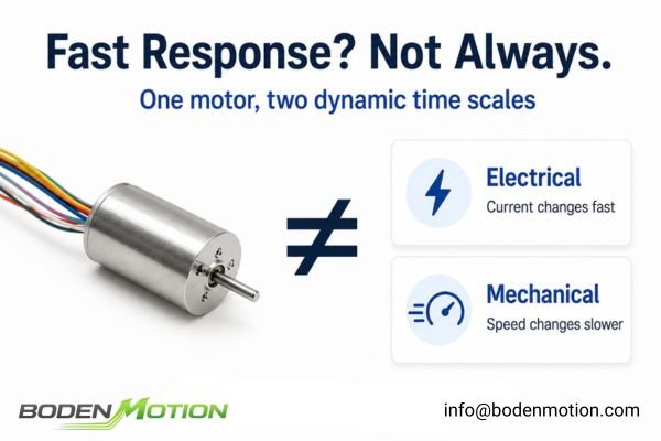
Engineers often select coreless DC motors for their "fast response," but this term can be misleading. Current might rise quickly while the mechanical system still accelerates slowly, leading to unexpected performance issues.
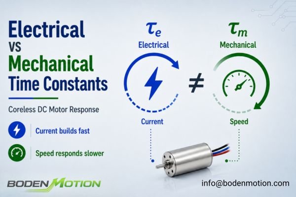
The reality is that a motor’s response involves at least two distinct dynamic time scales: the electrical time constant, which characterizes how quickly current can change, and the mechanical time constant, which characterizes how quickly motor speed responds mechanically.
Confusing these two can lead to poor driver selection, unrealistic acceleration targets, or a control loop that is much faster—or slower—than the physical motor system can support. For an OEM engineer designing a precision motion system, understanding the difference is not just academic; it's fundamental to achieving the required performance and stability1.
What Is the Electrical Time Constant of a Coreless DC Motor?
A motor can't produce torque instantly. The electrical time constant defines the speed limit for how quickly the torque-producing current can be established in the motor windings.
The electrical time constant (τe) is often approximated by the winding's inductance (L) and resistance (R), as τe = L / R. It describes how quickly current responds to a change in applied voltage, especially from a standstill.
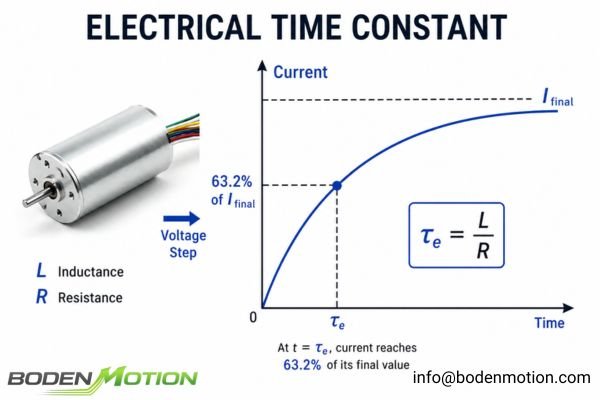
This simplified L/R model is most useful for understanding the initial current response before the motor's rotation generates significant back EMF. When a voltage step is applied, the winding's inductance opposes an instantaneous change in current, causing it to build exponentially. The time constant τe represents the time it takes for the current to reach approximately 63.2% of its final value in this simplified RL circuit scenario.
A smaller electrical time constant generally means:
- Faster current buildup and, therefore, faster torque generation.
- Higher potential bandwidth for the current control loop.
- More immediate response to high-frequency PWM switching.
ㅤ
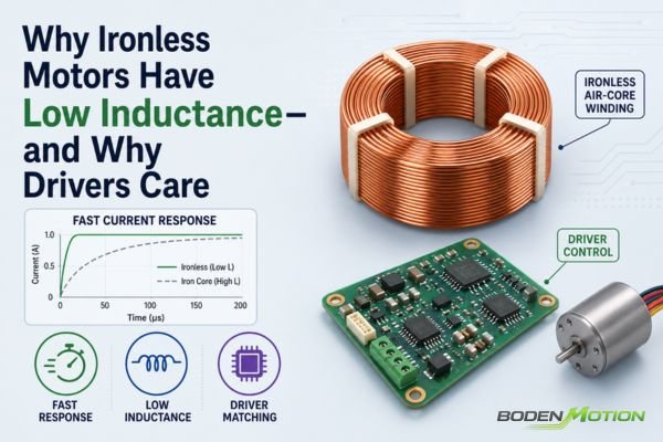
Coreless motors often have very low inductance because their windings are self-supporting and lack an iron core. This low L value, relative to the winding resistance, can contribute to a small electrical time constant and rapid electrical response. However, this can also introduce challenges like higher current ripple and increased sensitivity to driver performance, requiring careful system design.
What Is the Mechanical Time Constant?
Even when motor torque develops quickly, the shaft and connected mechanism still need time to accelerate. The mechanical time constant describes the characteristic speed response of the motor's mechanical system and helps indicate how quickly it can approach a new operating speed.
For a bare motor, the mechanical time constant (τm) is strongly influenced by rotor inertia and the motor's electromechanical characteristics. Once a load is connected, however, the actual acceleration response depends on the total inertia seen by the motor rather than on the bare-motor value alone.
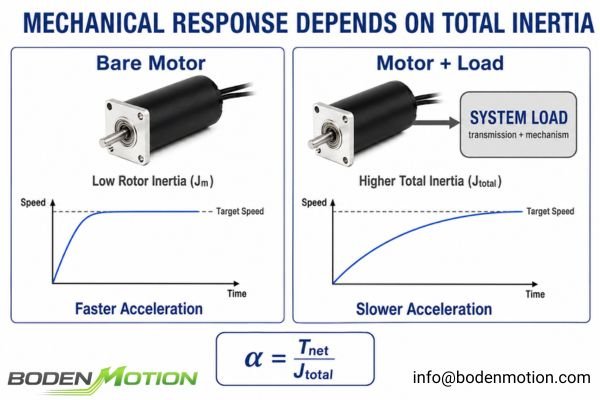
The acceleration of the system is governed by the net torque available after opposing load and friction torque are accounted for. This relationship can be expressed as α = T_net / J_total, where α is angular acceleration, T_net is the available net torque, and J_total is the total inertia reflected to the motor shaft. For the same available torque, a lower total inertia allows the system to accelerate more quickly.
Coreless motors benefit from their lightweight rotor structure and relatively low rotor inertia (Jm), which can support very fast bare-motor mechanical response. Across selected configurations in our coreless motor platform, bare-motor mechanical time constants can be as low as approximately 1.9 ms, depending on motor size, winding, and test conditions.
System-Level Observation:
A 1.9 ms bare-motor mechanical time constant should not be interpreted as a 1.9 ms response time for the final machine. Once the motor is connected to a gearbox, pulley, lead screw, or other load, the total inertia becomes approximatelyJ_total = J_motor + J_load_reflected + J_transmission2. Reflected load inertia, transmission dynamics, available torque, and control constraints can therefore make the complete system respond substantially more slowly than the motor alone.
Electrical vs Mechanical Time Constant: What Does Each One Tell You?
Confusing these two constants is a common source of design error. An electrically fast motor is not a guarantee of a mechanically fast system; they describe different parts of the same motion event.
The electrical time constant governs how fast current (and thus torque) can be created, while the mechanical time constant relates to how fast the rotor (and load) can accelerate once that torque is applied.
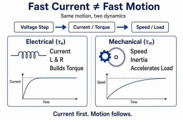
For engineers, treating these as interchangeable specifications can lead to significant problems in system integration and control. The following table breaks down what each constant tells you and why it matters.
| Comparison Item | Electrical Time Constant (τe) |
Mechanical Time Constant (τm) |
|---|---|---|
| Main Question | How quickly can winding current change? | How quickly can motor speed respond mechanically? |
| Primary Factors | Winding inductance (L) and resistance (R)3 |
Rotor inertia and motor electromechanical characteristics; system response is also affected by reflected load inertia and transmission dynamics |
| Primary Variable | Winding current | Rotor speed |
| Main Physical Effect | Current and electromagnetic torque buildup | Speed and acceleration response |
| Typical Timescale | Typically shorter, often from microseconds to milliseconds depending on the winding and motor design | Typically longer, often from milliseconds upward depending on the motor and connected mechanical system |
| Control Relevance | Current-loop bandwidth, PWM frequency, sampling, and driver voltage/current capability | Speed- and position-loop tuning, acceleration profile, and settling behavior |
| Load Sensitivity | Load affects current indirectly through speed, back EMF, and torque demand | Strongly affected at the system level by reflected load inertia, friction, gearing, and transmission characteristics |
| A Lower Value Generally Indicates | Faster electrical current response | Faster bare-motor mechanical response; actual machine response still depends on the connected load |
| Common Risk if Misinterpreted | Assuming fast current response automatically means fast machine motion | Treating the bare-motor time constant as the acceleration or settling time of the complete system |
What Happens During Startup? A Timeline of the Two Time Constants
An electrically fast motor does not guarantee an equally fast mechanical motion. The startup sequence is a dynamically coupled process where electrical and mechanical events overlap and influence each other.
During startup, current begins rising based on the electrical dynamics, generating torque that then accelerates the mechanical system based on its own dynamic properties.
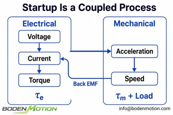
Let's trace this coupled process:
- Voltage Is Applied: The driver applies a voltage across the windings.
- Current Rises & Torque Builds: Current begins to rise, with its rate limited by the electrical dynamics (
V = IR + L(di/dt) + Keω). As soon as current exists, the motor produces electromagnetic torque.4 - System Begins Accelerating: Once the motor torque exceeds the opposing friction and load torque, the remaining net torque begins to accelerate the system's total inertia. The rate of acceleration is determined by the net torque and total inertia.
- Back EMF Builds: As the rotor speeds up, it generates a back EMF that opposes the supply voltage. This reduces the net voltage driving the current, dynamically altering the torque available for further acceleration.
- System Approaches Operating Speed: The motor continues to accelerate until the motor torque balances the total load torque, at which point it settles at its final operating speed.5
This flow is not strictly sequential but interactive:
Voltage Command ↔ Electrical Current Response (τe) ↔ Torque Production ↔ Mechanical Acceleration (τm + load dynamics) ↔ Speed Response
Why Load Inertia Can Dominate the Mechanical Response
A motor's datasheet might show an impressive mechanical time constant, but this value is for the motor alone. In real-world OEM systems, the connected load is what often defines the acceleration performance.
The total inertia that the motor must accelerate is the sum of its own rotor inertia and the inertia of the load reflected back to the motor shaft. In many applications, the reflected load inertia can dominate the total inertia.
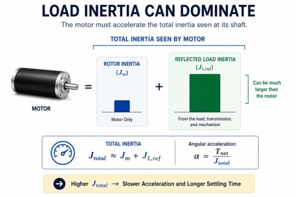
Consider these common scenarios:
- Robotic Joint: The motor's rotor inertia may be small, but the inertia of the entire robot arm and its payload can be substantially higher, becoming the dominant factor in joint acceleration.
- Lead Screw: The motor must accelerate both the screw itself and the reflected linear mass of the carriage. A heavy carriage will significantly slow the system's mechanical response.
- Gearbox: A gearbox is often used for inertia matching6. For a speed reduction ratio
N:1(whereN > 1), the load inertiaJLas seen by the motor is reduced toJL_reflected = JL / N². While this helps the motor accelerate the load, the gearbox's own inertia, friction, and compliance must also be factored into the system model.
Ignoring the full system inertia can lead to:7
- Significantly longer acceleration times than predicted.
- Higher peak current draw during startup.
- Increased settling time and control loop instability.
What OEM Engineers Should Provide When Evaluating Motor Response Time
Simply asking "Do you have a fast-response motor?" is insufficient. As with broader DC motor selection, a meaningful evaluation requires defining the required response within the context of the complete electromechanical system, including the load, driver, supply, and motion profile.
To properly evaluate a motor's suitability, it is essential to know how quickly the current, torque, and shaft speed must respond with the actual load attached, and under what control constraints.
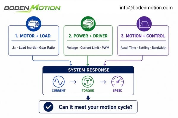
To help us at BODENMOTION evaluate whether a coreless DC motor can meet your required motion cycle, providing the following information is crucial:
- Motor Parameters: Rotor inertia, torque constant, winding resistance, and inductance8.
- Load & Mechanical System: Load inertia, gear ratio, friction torque.
- Driver & Power Supply: Supply voltage, driver current limit, PWM frequency.
- Motion Profile: Target acceleration/deceleration time, required rise time.
- Control Requirements: Allowable overshoot, settling time, and the desired bandwidth of the current, speed, and position loops.
These inputs also help determine which motor parameters can realistically be adjusted during selection. Depending on the application, winding options, operating voltage, encoder integration, and gearbox configuration can be evaluated together rather than treating the motor as an isolated, fixed component.
How Electrical and Mechanical Time Constants Affect Control-Loop Design
A fast coreless motor does not justify arbitrarily high control bandwidth. The control loops must be tuned to respect the physical limits imposed by both the electrical and mechanical dynamics of the system.
In a typical cascaded motion controller, the inner loops generally operate at higher bandwidth than the outer loops. The current loop interacts with the motor's electrical dynamics, while the speed loop must account for the mechanical dynamics of the complete system.
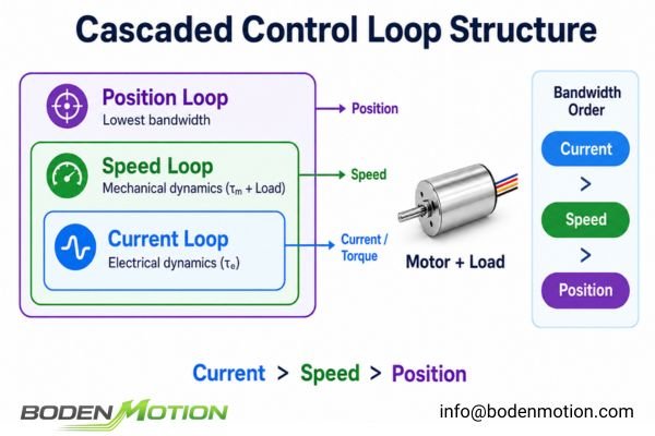
A well-designed motion controller often uses a cascaded structure: Current Loop → Speed Loop → Position Loop.
- Current Loop: This innermost loop directly controls torque. Its bandwidth must be high enough to manage the motor's electrical dynamics effectively.
- Speed Loop: This loop maintains a target speed. Its tuning is fundamentally tied to the mechanical dynamics of the motor plus the load. Its bandwidth is typically set lower than the current loop's.
- Position Loop: The outermost loop calculates a required speed to get to a target position. It relies on the underlying loops and typically has the lowest bandwidth in the cascade.
Mismatching these loops with the system's physical constants leads to common failures:
| Control Issue | Possible Result |
|---|---|
| Current loop bandwidth too low | Delayed or poorly regulated torque response |
| Current loop too aggressive | High-frequency current ripple or instability |
| Speed loop too aggressive for system inertia | Speed overshoot, oscillation, and long settling times9 |
| Load inertia underestimated in tuning | Slower-than-expected response, potential instability |
| Loop tuned on bare motor, used on loaded system | Poor performance or instability after installation |
Conclusion
Electrical and mechanical time constants describe two different but coupled aspects of a coreless motor's dynamic response. The electrical time constant (L/R) characterizes how quickly winding current—and therefore electromagnetic torque—can develop, while the mechanical response depends on how that torque accelerates the total inertia of the motor and connected load. A motor can therefore have a very fast electrical response without the complete system accelerating or settling equally quickly.
For OEM applications, "fast response" should be evaluated at the complete electromechanical-system level rather than from a single datasheet value. Load inertia, gearing, driver limits, transmission mechanics, and control tuning can all influence the final response. If you are designing a high-response system, BODENMOTION can help evaluate the motor, load, drive, and motion profile together to determine whether the selected configuration can meet the required acceleration and settling targets. Contact us at info@bodenmotion.com to discuss your application.
FAQ
Q1: What is the electrical time constant of a coreless DC motor?
It is a characteristic time related to the winding's current response, often approximated as L/R (inductance divided by resistance). It indicates how quickly current begins to change when voltage is applied.
Q2: What is the mechanical time constant of a coreless motor?
It characterizes how quickly a bare motor's speed responds mechanically to a change in operating condition. Rotor inertia and the motor's electromechanical characteristics strongly influence this value, while the actual system response also depends on reflected load inertia, friction, transmission dynamics, and available torque.
Q3: Why do coreless motors usually respond quickly?
Their windings can have relatively low inductance for a fast electrical response, while the lightweight coreless rotor provides low mechanical inertia for rapid acceleration, assuming the load is not dominant.
Q4: Does a low electrical time constant mean the motor accelerates quickly?
Not necessarily. A low electrical time constant means torque can be generated quickly, but the actual mechanical acceleration still depends on the net available torque and the total inertia of the rotor plus the connected load.
Q5: What information should OEM engineers provide for response-time evaluation?
Provide motor parameters, load inertia, gear ratio, supply voltage, current limits, and the required motion profile, including acceleration, deceleration, and settling time requirements for the complete system.
PI, "10 Key Questions About Precision Motion and Positioning Systems". Highlights the importance of understanding system-level dynamics and component interactions when designing precision motion systems for reliable performance and stability. ↩
Motion Control Tips, "How do gearmotors impact reflected mass inertia from the load?". Explains how motor inertia, reflected load inertia, and transmission inertia combine to influence the total inertia seen by the motor. ↩
MOSRAC, "Motor Constant: The Hidden Variable Behind Precision and Performance". Provides background on motor electrical parameters, including winding inductance and resistance, which determine the winding's L/R electrical time constant. ↩
Michigan State University, "Torque on a Current Loop: Motors and Meters". Explains how current-carrying conductors in a magnetic field produce electromagnetic torque, providing the physical basis for torque generation once winding current begins to flow. ↩
Rice University, "The DC Motor". Describes the steady-state condition in which motor torque balances the opposing load torque and net acceleration falls to zero. ↩
Firgelli Automations, "Motor Inertia Matching Ratio Interactive Calculator". Discusses the use of gearing to reduce reflected load inertia at the motor shaft and improve inertia matching between the motor and load. ↩
ScienceDirect Topics, "Motor Inertia - an overview". Provides background on the role of motor and load inertia in acceleration, dynamic response, and motion-control performance. ↩
MathWorks, "DC motor model with electrical and torque characteristics and fault capabilities". Identifies rotor inertia, torque constant, winding resistance, and inductance as fundamental parameters in a DC motor's electrical and mechanical model. ↩
Nature Index, "Inertia Identification and Speed Control in Electrical Drive Systems". Provides research context on the relationship between inertia identification and speed-control performance in electrical drive systems. ↩