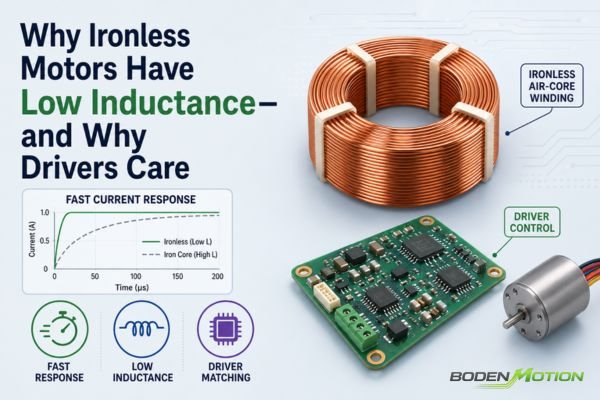
Your precision system needs to start and stop on a dime, but the motor seems to be fighting every move. This sluggishness often points back to a single, critical parameter: inertia.
A coreless motor's characteristically low rotor inertia makes it easier for a system to achieve rapid acceleration, deceleration, and direction changes, especially when the motor's own inertia is a significant part of the total system inertia.
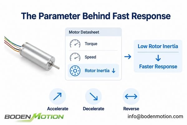
From our experience evaluating dynamic applications for OEMs, a motor's datasheet torque and speed are only part of the story. The dynamic capability—how quickly the motor can change its state—is often what separates a high-performance machine from a mediocre one. This is where understanding inertia becomes crucial, and it’s the primary reason engineers turn to coreless motor technology1 for the most demanding dynamic applications.
What Is Motor Inertia and Why Does It Matter?
Many engineers focus on peak torque but find their system still can't accelerate fast enough. The missing piece of the puzzle is often rotational inertia, the physical resistance of an object to changes in its rotational speed.
Rotational inertia (J) is a measure of an object's resistance to angular acceleration. For a given amount of torque (T), a lower inertia allows for a higher rate of angular acceleration (α), as described by the fundamental equation of motion: α = T / J.
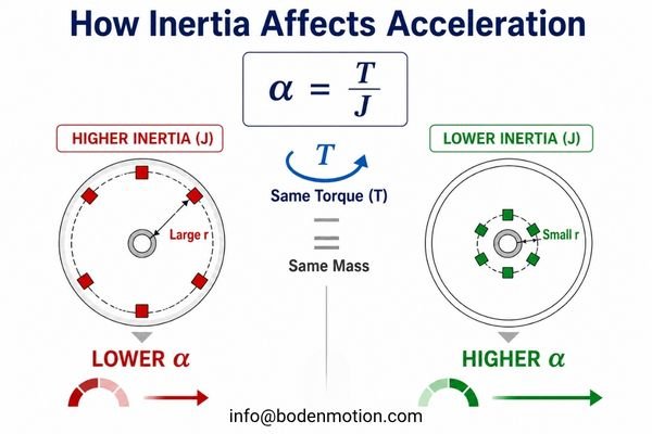
In practical terms, the motor's own rotor inertia contributes to the total torque required during acceleration and deceleration. The higher the rotor inertia, the more inertial torque is required to change the motor's speed. A high-inertia rotor behaves like a flywheel: it requires more torque to achieve the same acceleration or deceleration, and with the same available torque, it takes longer to speed up or slow down.
Common OEM Mistake:
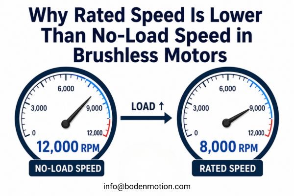
A frequent misunderstanding is equating low inertia with higher maximum speed. Inertia does not set a motor's steady-state or no-load speed; for a given motor, speed is governed primarily by the applied voltage, back-EMF characteristics, and operating load. Instead, inertia directly influences how quickly the motor can accelerate or decelerate for a given available torque. For applications requiring rapid, repeated changes in velocity, rotor inertia can therefore be more important than no-load speed when evaluating dynamic performance.
Why Do Coreless Motors Have Lower Rotor Inertia?
The term "coreless motor" can refer to more than one motor architecture. In a brushed coreless DC motor, the rotating armature uses a lightweight, self-supporting winding instead of a conventional laminated iron core. In brushless ironless or slotless designs, the winding is stationary, so rotor inertia depends on the permanent-magnet rotor construction rather than on a rotating coreless winding.
The low-inertia advantage is most direct in brushed coreless DC motors, where eliminating the laminated iron armature substantially reduces rotating mass. Brushless coreless designs can also be engineered for low rotor inertia, but the structural mechanism is different.
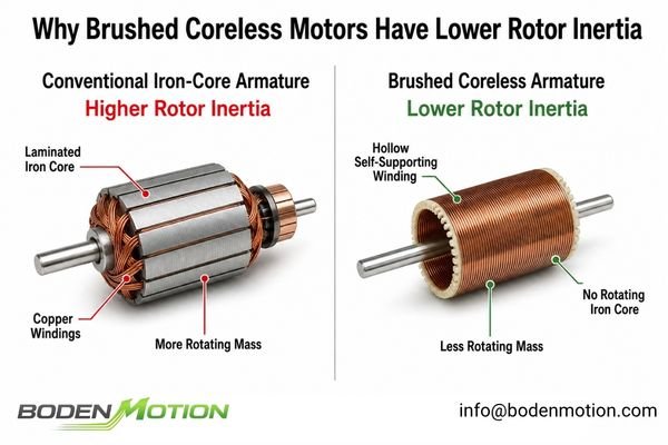
For a typical brushed coreless DC motor, the structural difference can be summarized as follows:
- Conventional Iron-Core DC Motor: Copper windings are wound around a laminated iron armature. This rotating assembly contributes more mass and inertia to the rotor.
- Brushed Coreless DC Motor: The rotor uses a hollow, self-supporting winding without a rotating laminated iron core. This reduction in rotating mass is the main reason this architecture can achieve very low rotor inertia.
In this brushed coreless architecture, the structural difference directly affects rotational inertia. In simplified terms, inertia increases with rotating mass and increases strongly as that mass is distributed farther from the axis of rotation (J ∝ mr²). By reducing the amount of rotating iron and using a lightweight self-supporting winding, a brushed coreless motor can achieve substantially lower rotor inertia than a comparable iron-core design2.
The same ironless armature structure also eliminates cogging torque3 and typically results in low winding inductance, which can further support smooth and responsive motor behavior.
How Does Low Inertia Change Motor Performance?
Engineers often specify a coreless motor when they find their system response is too slow. The low rotor inertia can directly enable tangible performance gains in dynamic systems.
The primary benefit of low rotor inertia is a higher potential for dynamic response, which can support faster acceleration, shorter settling times, and more rapid direction reversals for a given amount of available torque.
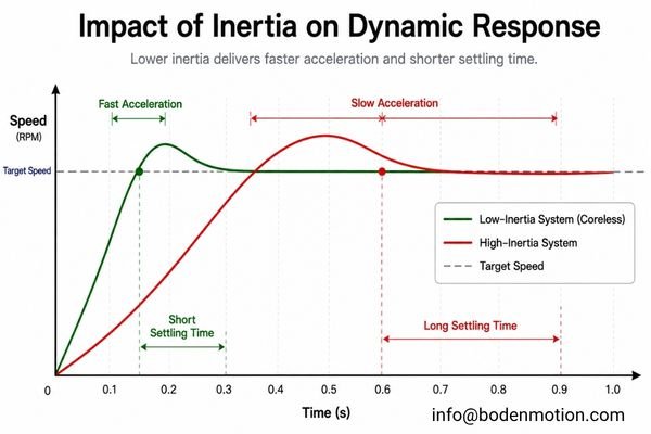
In OEM projects, we've seen the switch to a coreless motor solve persistent issues with system throughput and precision. Here's how low inertia directly impacts performance:
Faster Acceleration and Deceleration
From α = T / J, it is clear that for the same available torque, reducing inertia increases the potential angular acceleration. In applications such as pick-and-place robotics or medical sample handling, this can contribute to shorter move times and higher throughput.
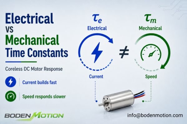
In a simplified first-order motor model, dynamic response can also be described by the mechanical time constant, which indicates how quickly an unloaded motor approaches its steady-state speed after a voltage step. Selected configurations across our coreless motor platform can achieve mechanical time constants as low as approximately 1.9 ms, depending on motor size, winding, and operating conditions.
Faster Direction Reversal
For applications involving oscillatory motion, such as optical scanners, the ability to reverse direction quickly is paramount. Lower rotor inertia reduces the torque and mechanical energy associated with decelerating and re-accelerating the rotor itself, which can make frequent reversals easier to achieve.
Supports Faster Dynamic Response
In closed-loop servo systems, low rotor inertia can support faster settling and higher achievable control bandwidth4 when the controller, feedback system, and mechanical structure are designed accordingly. This means the motor can more accurately track a complex, rapidly changing target position or velocity profile.
Rotor Inertia vs Total System Inertia
It's tempting to think that simply choosing a low-inertia motor will guarantee a fast system. In the real world, the motor is only one part of the equation.
A low-inertia motor does not automatically create a low-inertia system. The total inertia that the motor must overcome is the sum of its own rotor inertia plus the inertia of the load and any transmission components, as reflected back to the motor shaft.
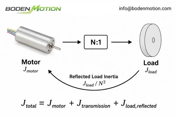
This system-level representation can be simplified as:
J_total = J_motor + J_transmission + J_load_reflected
The key term here is J_load_reflected. When a gearbox with a reduction ratio of N:1 is used, the inertia of the load is reduced by the square of the gear ratio as it's reflected back to the motor (J_load_reflected = J_load / N²)5.
System-Level Observation:
As an engineering guideline, the ratio of reflected load inertia to motor inertia is useful when evaluating how much the motor's own inertia contributes to system dynamics6. When motor inertia remains a meaningful portion of the total inertia, reducing rotor inertia can noticeably improve acceleration and response. As reflected load inertia becomes increasingly dominant, however, further reductions in motor inertia have a progressively smaller effect on total system behavior.
Which Applications Benefit Most from Low-Inertia Coreless Motors?
The theoretical benefits of low inertia are clear, but where does this technology provide the most practical value? The answer lies in applications defined by rapid changes in motion.
Low-inertia coreless motors are most beneficial in applications that demand high-frequency start-stop cycles, rapid direction changes, or precise tracking of dynamic motion profiles, where minimizing acceleration time is critical to system performance.
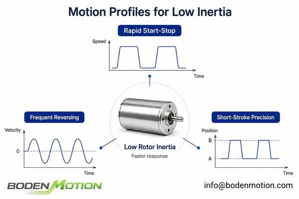
Instead of just listing industries, it's more useful to think in terms of motion requirements. Coreless motors excel at:
- Rapid Start-Stop Motion:
- Robotic end-effectors and small joints7
- Medical and laboratory automation (pipetting, sample handling)
- Pick-and-place machines
- Frequent Reversing and Oscillation:
- Optical scanning, beam steering, and chopper systems
- Haptic feedback devices
- Short-Stroke, High-Precision Positioning:
- Semiconductor inspection equipment
- Lens focusing mechanisms and autofocus systems
- Miniature precision actuators and X-Y stages
In these applications, reducing rotor inertia decreases the portion of available torque required to accelerate and decelerate the motor itself8, leaving more of the system's dynamic capability available for moving the actual load.
When Is a Coreless Motor Not the Best Choice?
Despite their advantages, coreless motors are not a universal solution. In some scenarios, the benefits of low inertia are marginal, and a traditional iron-core motor may be a more practical choice.
A coreless motor's dynamic advantage is less significant in applications with constant-speed operation, extremely high reflected load inertia, or where sustained thermal load is the primary design driver.
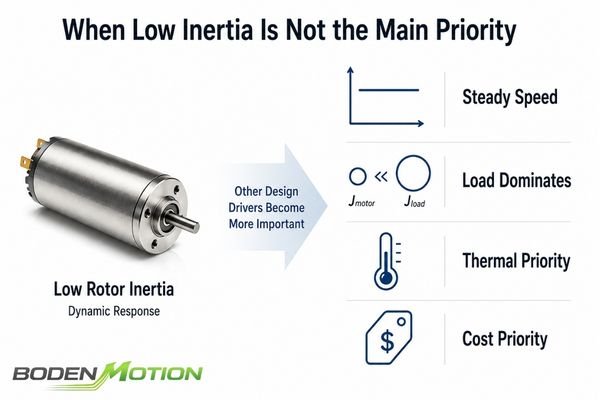
Specifying a high-performance coreless motor for the wrong job is a common form of over-engineering. The advantage of low rotor inertia diminishes when your application involves:
- Mostly Steady-Speed Operation: For applications like fans or pumps running at a constant speed, the initial acceleration phase is a tiny fraction of the total runtime.
- Very High Reflected Load Inertia: If the load inertia overwhelmingly dominates the system, the benefit of the motor's low inertia is minimal.9 The system's dynamics will be dictated by the load, not the motor.
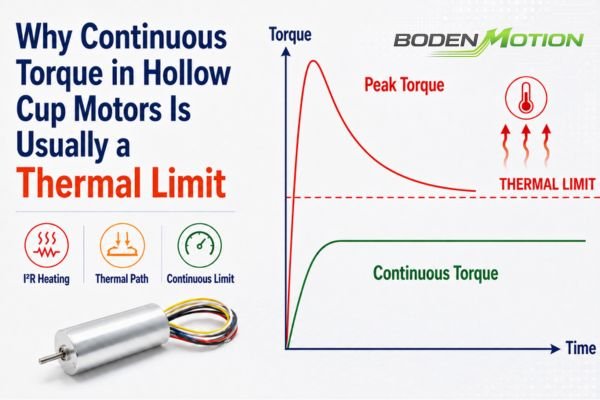
- High, Sustained Thermal Loads: When continuous torque and sustained thermal loading are the main challenges, engineers should compare the actual continuous torque ratings, thermal resistances, and cooling conditions of specific motor candidates, rather than assuming one topology is always better.
- Severe Cost Constraints: The manufacturing of the self-supporting coreless winding can make these motors more expensive than conventional iron-core counterparts for the same basic specifications.
| Application Characteristic | Low-Inertia Advantage Is More Significant When... | Low-Inertia Advantage Is Less Significant When... |
|---|---|---|
| Primary Motion | Rapid start-stop cycles, frequent reversing, or short dynamic moves | Long periods of continuous, steady-speed operation |
| Inertia Relationship | Motor inertia remains a meaningful portion of the total inertia seen at the motor shaft | Reflected load inertia strongly dominates the total system inertia |
| Torque Profile | Frequent acceleration and deceleration require substantial transient torque | Sustained continuous torque and thermal loading dominate the duty cycle |
| Key Performance Metric | Acceleration, cycle time, dynamic response, or achievable control bandwidth | Steady-state performance, thermal capability, efficiency, or cost |
How Should Engineers Select a Coreless Motor for a Low-Inertia Application?
Selecting the right motor requires a systems-level approach. You cannot just pick the motor with the lowest inertia; you must match it to your specific load and motion goals.
To properly select a coreless motor, engineers must define the system's complete motion profile, calculate the total system inertia, and determine the peak and RMS torque required to achieve the target acceleration and duty cycle.
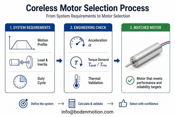
A successful selection hinges on having clear answers to these questions:
- Motion Profile: What is the target speed, position, and time allowed for acceleration, constant velocity, deceleration, and dwell?
- Total System Inertia (
J_total): What is the sum of the motor, transmission, and reflected load inertia? - Required Acceleration (
α): Based on the motion profile, what is the required angular acceleration? - Required Torque (
T_peak,T_rms):- Calculate the peak torque needed for acceleration:
T_peak = (J_total × α) + T_load.T_loadincludes friction, gravity, process forces, etc. - Calculate the Root Mean Square (RMS) torque over the entire duty cycle to check against the motor's continuous torque rating.10
- Calculate the peak torque needed for acceleration:
- Thermal Validation: Will the motor operate within its thermal limits based on the calculated RMS torque and current? Consider the ambient temperature and any available heat sinking.
Starting with these parameters allows you to filter motor candidates effectively and ensure the one you choose can not only perform the task, but do so reliably for the life of your product.
Conclusion
The key advantage of a coreless motor in dynamic applications is that it reduces the motor's own contribution to total system inertia. This reduces the torque and time required to change rotational speed. However, the real engineering benefit depends on how significant the motor's inertia is relative to the load, transmission, and required motion profile.
For OEM engineers designing dynamic systems, the first step is to analyze your complete load and motion requirements. If your application's performance is limited by acceleration time or dynamic response, our team at BODENMOTION can help. Contact us at info@bodenmotion.com with your system parameters—including load inertia, motion profile, and duty cycle—to evaluate if a low-inertia coreless motor is the right solution.
FAQ
Why do coreless motors have low inertia?
Coreless motors have low inertia because their rotor consists of a lightweight, self-supporting winding without a heavy, rotating iron core. This design significantly reduces the rotor's mass and its resistance to angular acceleration.
Do coreless motors accelerate faster?
For a given amount of torque, a coreless motor's lower rotor inertia allows it to achieve higher rates of angular acceleration compared to an iron-core motor. However, final system acceleration depends on the total inertia of the entire system (motor + load).
Does low inertia mean higher motor speed?
No. Inertia affects the rate of acceleration, not the maximum possible speed (RPM). A motor's maximum speed is primarily determined by its design, applied voltage, and back-EMF constant.
Is a coreless motor always better than an iron-core motor?
Not always. For steady-speed applications, applications dominated by a very high reflected load inertia, or where continuous thermal load is more critical than dynamic response, a conventional iron-core motor can be a more practical and cost-effective choice.
How does load inertia affect coreless motor performance?
The motor must accelerate both its own rotor and the load. Even with a low-inertia motor, a very high load inertia will dominate the system's dynamics and require high torque to accelerate, reducing the relative benefit of the motor's low inertia.
Are coreless motors suitable for high-inertia loads?
They can be, depending on the required motion profile and available torque. A gearbox can reduce the load inertia reflected back to the motor by the square of the reduction ratio, which may make a high-inertia load easier for the motor to accelerate. However, the gearbox ratio must also be selected based on the required output speed, torque, efficiency, backlash, and overall drivetrain behavior.
Electromate, Coreless vs Iron-Core: Why maxon Uses Coreless Motor Design in Precision Motion Control Applications. The comparison explains that eliminating the iron rotor core reduces mechanical inertia, enabling rapid acceleration and deceleration and supporting high-dynamic precision motion applications. ↩
FIRGELLI Automations, Cored vs Coreless DC Motors: What Actually Changes? The article compares conventional iron-core and brushed coreless DC motor construction and explains that removing the rotating iron armature produces a much lower-inertia rotor. ↩
Precision Microdrives, Cogging Torque in Permanent Magnet Motors. The article explains the magnetic origin of cogging torque and states that coreless motors do not suffer from conventional cogging because their construction removes the periodic magnetic alignment responsible for it. ↩
INMOCO, Does Inertia Matching Still Matter in Servo System Design? The article links lower total system inertia and appropriate mechanical stiffness with higher achievable bandwidth and improved move-and-settle performance. Its discussion is system-level rather than a rotor-inertia-only relationship. ↩
Southern Illinois University, ET 438a Control Systems Technology, Laboratory 4: Modeling Control Systems with MATLAB/Simulink. The gear-system model shows that rotational inertia reflected through a gearbox changes with the square of the gear ratio; with a reduction ratio defined as N:1, the reflected load inertia becomes J_load / N². ↩
Oriental Motor, Motor Sizing Basics Part 2: How to Calculate Load Inertia. The guide defines inertia ratio using load inertia, reflected through the gearbox when applicable, relative to motor rotor inertia, and uses this relationship when evaluating motor sizing and dynamic compatibility. ↩
Portescap, Innovative Motion Solutions Fuel Latest Robotics Trends. The whitepaper discusses miniature motor use in robotic end effectors and compact joint-related applications, including grippers, elbow and finger mechanisms, joint positioning, and robotic joint manipulation. ↩
Portescap, Motor Selection Basics: Inertia and Power and Torque Requirements. The article separates the torque required to accelerate motor inertia from that required to accelerate the load, showing that lower motor inertia reduces the inertial torque needed to change the motor's own speed. ↩
Portescap, Motor Selection Basics: Inertia and Power and Torque Requirements. The article expresses acceleration torque in terms of combined motor and load inertia and discusses load-to-motor inertia matching. This supports the system-level conclusion that when load inertia strongly dominates, further reductions in motor inertia have a progressively smaller effect on total dynamic behavior. ↩
Kollmorgen, How to Calculate RMS Torque. The article calculates RMS torque from the torque and duration of each segment in a motion cycle and describes it as the equivalent continuous torque requirement used for motor sizing. ↩