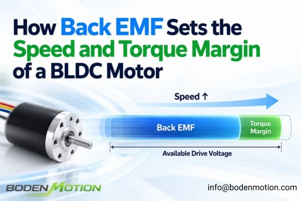
Precious-metal brush coreless DC motors are often chosen for their smooth operation and low starting voltage, but their long-term reliability depends heavily on the electrical and physical environment in which they operate. Performance can degrade if the drive circuit is not designed around the specific behavior of the brush–commutator contact.
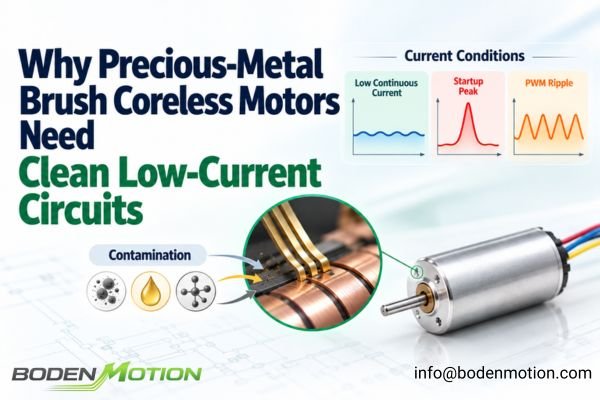
In a brushed coreless motor, the precious-metal brush is a sensitive electrical contact that performs best in a low-current, well-controlled electrical environment. Its reliability is directly influenced by continuous current, peak startup current, PWM-induced current ripple, and contact-surface contamination.
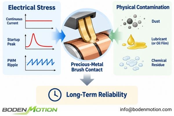
The brush system is not only a mechanical wear component; it is also an electrical contact that repeatedly transfers current between the stationary terminals and the rotating commutator. Precious-metal systems are valued for low contact resistance, low starting voltage, and low electrical noise1, but these advantages are strongest within a controlled operating region. The engineering question is therefore not simply whether a precious-metal brush motor can operate at a given voltage, but whether the complete current profile, start-stop duty, PWM strategy, electrical environment, and physical operating conditions remain compatible with reliable brush contact over the required service life.
Why Precious-Metal Brushes Work Well at Low Voltage and Low Current
The primary advantage of a precious-metal brush system is its performance in low-power drive applications. Its material and contact characteristics are well suited to maintaining stable, low-resistance electrical contact when the required current remains relatively low.
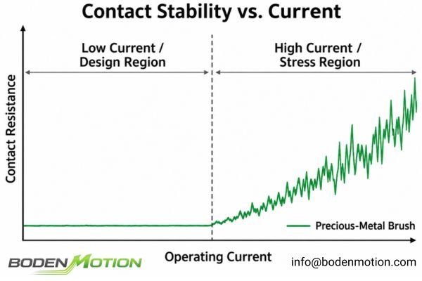
The advantage of a precious-metal brush is strongest when the application operates in a low-current, clean-contact regime. At lower current levels, the brush–commutator interface experiences reduced localized heating, lower arcing energy, and less severe surface erosion during commutation.
These characteristics make precious-metal brush coreless motors well suited to compact systems such as:
- Precision instruments
- Small medical pumps and diagnostic devices
- Optical focusing mechanisms
- Portable battery-powered equipment
- Low-power actuators and sensor positioners
A practical example is the BDCM1219 precious-metal brushed coreless DC motor, a compact Φ12 × 19 mm platform available with multiple winding options. Its low starting voltage, low electrical noise, and compact construction are representative of the type of low-power OEM application where precious-metal brush commutation can provide clear advantages.
At these operating points, the brush and commutator can transfer current without the higher thermal and electrical stress associated with large current density2. This helps preserve the low starting voltage, stable contact behavior, and low electrical noise that designers expect from this type of commutation system.
However, these advantages should not be interpreted as a universal property independent of operating conditions. As current, startup frequency, or electrical transient energy increases, the contact system may move progressively away from the region in which precious-metal brushes offer their strongest advantages.
Current Density and Brush–Commutator Contact Stress
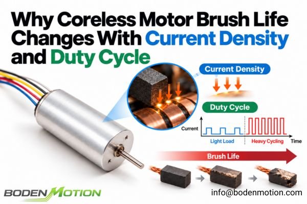
The total motor current must pass through a very small physical contact region between the brush tip and the commutator surface. As current rises, the electrical and thermal stress concentrated at this interface also increases.
A motor that appears acceptable based on average current can still experience excessive brush and commutator stress if the instantaneous current density becomes too high. This can increase localized heating, arcing energy, and material transfer between the contact surfaces.

Several effects become increasingly important as contact current rises:
- Localized Heating: Even relatively low contact resistance produces
I²Rloss. Because this heat is generated over a small contact area, higher current can raise the local surface temperature substantially. - Higher Arcing Energy: As the brush transitions between commutator segments, an electrical arc can form. Higher instantaneous current and greater stored winding energy can increase the energy released during this event.
- Material Transfer: Repeated arcing can transfer microscopic amounts of material between the brush and commutator surfaces3, gradually changing the surface condition and contact resistance.
- Accelerated Wear: Electrical erosion and thermal stress can combine with normal mechanical wear, reducing the useful life of the commutation system.
It is therefore important to distinguish between two current conditions:
- Continuous Current: Determines sustained thermal loading and contributes to the long-term wear rate.
- Peak Current: Determines short-duration contact stress and can become especially important during startup, rapid load changes, reversals, or near-stall conditions.
A motor should therefore not be evaluated only from its nominal operating current. The shape of the current profile and the magnitude of repeated peaks can be just as important to long-term brush reliability.
In practice, OEM engineers do not normally calculate brush-contact current density directly because the effective microscopic contact area depends on the specific brush and commutator design. The motor's specified current limits, transient-current conditions, duty cycle, and supplier validation data are therefore more practical engineering references.
Startup Current and Repeated Start-Stop Stress
Startup is one of the most demanding electrical conditions for a brushed DC motor because back EMF has not yet developed. This means the initial current can be substantially higher than the normal running current.
For precious-metal brush motors, repeated startup events can create significant cumulative contact stress even when the average operating current remains low. Each start exposes the brush–commutator interface to a high-current condition while back EMF is approximately zero.
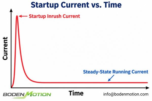
At zero speed, there is essentially no back EMF opposing the applied voltage4. The initial current is therefore limited mainly by the total circuit resistance and any current limiting implemented by the driver.
This can create a short but significant electrical and thermal event at the contact interface. In applications that start only occasionally, the effect may be limited. In systems that repeatedly start, stop, reverse, or index, however, the same high-current condition may occur thousands of times during normal operation.
| Application A: Continuous Run | Application B: Frequent Start-Stop |
|---|---|
| Motor starts once. | Motor starts and stops every second. |
| Runs at light load for minutes. | Each operating event is short. |
| Startup stress is infrequent. | Startup stress is repeatedly accumulated. |
| Average current reflects most of the duty cycle. | Average current can hide repeated current peaks. |
A useful qualitative screening framework is:
Peak Current × Peak Duration × Start Frequency
This is not a lifetime calculation formula. Instead, it is a practical way to avoid judging the application from average current alone.
A low average current does not necessarily mean a low-stress brush environment if the motor repeatedly experiences high current at startup. Ignoring this distinction can significantly shorten service life.
PWM, Low Motor Inductance, and Current Ripple
Pulse-width modulation is widely used to control the speed and torque of brushed DC motors. In a coreless motor, however, the relatively low winding inductance means the electrical current can respond quickly to each PWM voltage pulse.
The key parameter is the actual winding-current waveform rather than PWM frequency alone. Bus voltage, winding inductance, PWM frequency and switching scheme, duty cycle, and driver current control together determine the current ripple and instantaneous current experienced by the brush contact.
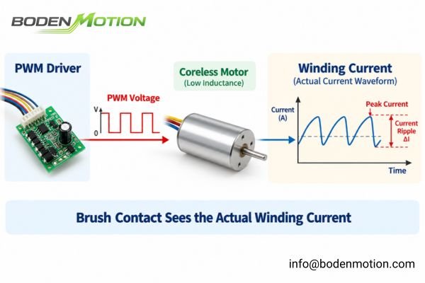
The main variables should be evaluated as a system:
- Motor Inductance: Coreless motors generally have relatively low inductance, allowing current to rise and fall rapidly in response to applied PWM voltage.
- Supply Voltage: A higher bus voltage increases
dI/dt, which can increase the magnitude of current ripple if the rest of the drive system is unchanged. - PWM Frequency and Switching Scheme: Increasing PWM frequency generally reduces winding-current ripple, but the resulting waveform also depends on the driver's switching strategy, control architecture, EMI behavior, bus voltage, and motor inductance.
- Duty Cycle: Changes the average applied voltage and affects the operating point at which current ripple must be evaluated.
- Current Limiting: The response speed and control method of the driver determine how effectively current peaks are constrained.
There is therefore no universal “best” PWM frequency for every coreless motor.
High current ripple can make the instantaneous current through the brush substantially higher than the average current.5 If this higher current coincides with mechanical commutation, it can increase localized heating and arcing energy at the brush–commutator interface.
This is why the motor and driver should not be selected independently. A suitable motor can perform poorly when paired with an unsuitable PWM strategy, while the same motor may operate reliably when the current waveform is properly controlled.
EMI Suppression, Wiring, and Driver Integration
A clean electrical environment is not defined only by the magnitude of the motor current. Mechanical commutation also creates high-frequency voltage disturbances and broadband electrical noise that must be controlled at the system level.
Low-noise brush contact is only one part of electromagnetic compatibility. Effective EMI control depends on the combined behavior of the motor, driver, PCB layout, wiring, grounding, suppression components, and cable routing.
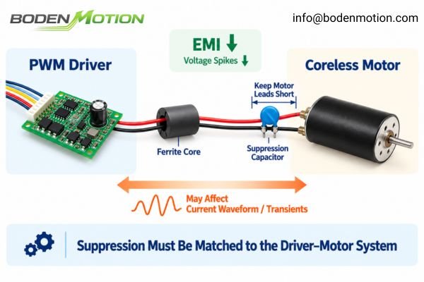
Electrical arcing at the brush–commutator interface can produce6:
- Voltage Spikes: Fast transients that may disturb or stress nearby electronics.
- Conducted EMI: Noise that propagates through the motor power leads.
- Radiated EMI: High-frequency energy that can interfere with nearby sensors, analog circuitry, or communication systems.
Common suppression measures include:
- Capacitors
- RC suppression networks
- Ferrite beads or ferrite cores
- Short and well-routed motor leads
- Controlled grounding and PCB return paths
However, these components should not be added independently of the motor driver.
For PWM-controlled systems, suppression components should be selected with consideration for the controller's output-stage requirements. An incorrectly selected capacitor can interact with motor inductance, alter the PWM current waveform, increase transient current, or affect driver behavior.
The correct design objective is therefore not simply to “filter the motor.” It is to manage the complete electrical path from the power stage through the motor and back into the control electronics.
Why Physical Contamination Changes Contact Reliability
The word “clean” also has a literal mechanical meaning. Because electrical conduction occurs through a very small contact region, foreign material on the brush or commutator surface can significantly change contact behavior.
Dust, lubricant, chemical vapor, residue, or condensation can form insulating or abrasive films on the contact surfaces. This can increase contact resistance, destabilize startup, raise electrical noise, and accelerate wear over time.
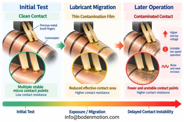
Potential sources include:
- Dust from the surrounding environment
- Oil or grease migration from gearheads or bearings
- Vapors from adhesives
- Cleaning-chemical residues
- Condensation in high-humidity environments
A contaminated contact surface can behave differently even when the motor's supply voltage and mechanical load have not changed.7
Typical symptoms may include:
- Higher required startup voltage
- Intermittent startup
- Unstable low-speed operation
- Torque fluctuation
- Increased contact resistance
- Higher electrical noise
Lubricant migration from a nearby gearbox or bearing system is one integration risk that deserves particular attention. A motor may pass initial functional testing but develop contact instability later if oil vapor or migrated lubricant gradually reaches the commutator surface.
This is why motor qualification should include not only initial electrical performance but also the expected long-term operating environment.
When a Precious-Metal Brush Motor May Not Be the Right Choice
Precious-metal brush motors are highly effective within the operating region for which their contact system is suited, but not every application should be optimized around this commutation method.
When the application requires sustained high current, repeated high-energy startup events, severe reversing duty, or operation in a difficult contamination environment, the engineering question may shift from “How should this precious-metal brush motor be driven?” to “Is this still the appropriate commutation system?”
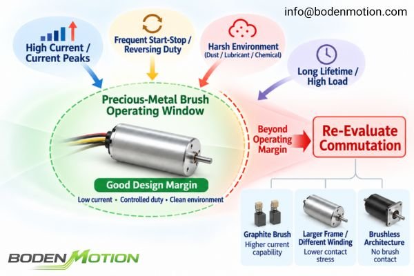
Applications that deserve additional review include those with:
- High continuous current relative to the motor size8
- Repeated high startup or stall-current events
- Frequent start-stop or reversing duty
- High mechanical load at very low speed
- Severe lubricant, dust, or chemical exposure
- Long lifetime targets combined with elevated contact stress
- Drive electronics that cannot adequately control current ripple or peak current
This does not mean that a precious-metal brush motor automatically fails under these conditions. Actual suitability depends on the specific motor design, brush geometry, winding resistance, driver behavior, load profile, operating temperature, and required lifetime.
The important point is that the commutation system should be treated as a design choice rather than a fixed assumption9.
If the application moves significantly outside the low-current, controlled-contact region, engineers should evaluate whether a different winding, a larger motor frame, graphite-brush commutation, or a brushless motor architecture would provide a more robust operating margin. For applications where commutation choice becomes the main design question, the comparison between precious-metal and graphite brush coreless motors provides a useful reference for evaluating current capability, startup duty, operating cycle, and lifetime requirements.
This boundary-based approach is especially useful during early motor selection because it prevents excessive effort from being spent optimizing a motor-driver combination that is fundamentally mismatched to the application's duty cycle.
How OEM Engineers Should Evaluate a Precious-Metal Brush Motor Circuit
A successful integration requires the motor, driver, load, and operating environment to be evaluated as one system. Voltage, speed, and torque alone are not sufficient to determine brush-contact reliability.
OEM engineers should evaluate continuous current, startup current, peak duration, start-stop frequency, PWM current ripple, EMI requirements, operating temperature, contamination risk, and expected lifetime together before approving the motor for production.
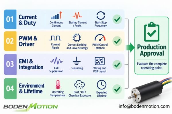
A practical evaluation checklist includes:
| Application Condition | What to Check |
|---|---|
| Very low supply voltage | Startup reliability and contact stability |
| Low continuous current | Suitability for the intended precious-metal contact regime |
| High startup current | Peak magnitude, duration, and driver current limiting |
| Frequent start-stop duty | Cumulative contact and commutation stress |
| PWM control10 | Actual winding-current ripple, not PWM frequency alone |
| Sensitive electronics nearby | EMI suppression, wiring, grounding, and PCB layout |
| Dust, oil, or chemical exposure | Contact-surface contamination risk |
| Long lifetime requirement | Current density, duty cycle, temperature, and environmental exposure |
| Very low-speed operation | Contact stability, friction, and voltage-control resolution |
A Simple Evaluation Flow
- Check Continuous Current: Confirm that sustained current remains within the motor's specified operating range.
- Check Startup Current and Duration: Evaluate the magnitude and duration of the initial current peak.
- Check Start Frequency: Determine how often the motor is exposed to repeated high-current startup events.
- Check the Current Waveform: If PWM is used, evaluate the actual winding-current ripple and peak current.
- Check Driver Interaction: Confirm that current limiting, PWM strategy, and suppression components are compatible with the motor.
- Check Noise and EMI: Evaluate the complete motor-driver-wiring system rather than the motor in isolation.
- Check Environmental Cleanliness: Assess whether contamination can reach the brush–commutator interface during the product's expected service life.
- Check the Commutation Choice: If the operating conditions remain highly stressful, reconsider whether precious-metal brush commutation is the appropriate architecture.
The goal is to move motor selection away from a simple voltage-and-speed comparison and toward a complete evaluation11 of the electrical, mechanical, and environmental operating point.
Conclusion
Precious-metal brush coreless motors perform particularly well in low-voltage, low-current applications where smooth motion, low starting voltage, and low electrical noise are important. Their reliability, however, depends on maintaining an operating environment that limits excessive current density, startup stress, arcing energy, current ripple, and contact contamination. The reliability chain is straightforward: current conditions affect heating and commutation energy, which influence contact-surface condition, contact resistance, wear, and ultimately service life.
For OEM engineers, the correct approach is to evaluate the motor together with the driver, duty cycle, load, EMI environment, and long-term contamination risk. For projects involving precious-metal brush motors, BODENMOTION's coreless motor solutions can be evaluated against these system-level requirements. OEM teams can provide their supply voltage, continuous and startup current, PWM strategy, load cycle, operating environment, and lifetime target to info@bodenmotion.com for engineering evaluation.
FAQ
Q1: Why are precious-metal brushes suitable for low-current applications?
Their contact characteristics provide stable conduction with low contact resistance and low electrical noise at low power levels, making them suitable for compact battery-powered, precision, and low-power motion systems.
Q2: Can a precious-metal brush motor handle high startup current?
Short startup-current peaks may be acceptable within the motor's specified operating limits, but excessive peak magnitude, duration, or repetition frequency can substantially increase electrical stress on the brush and commutator and accelerate wear.
Q3: Is PWM control bad for precious-metal brush motors?
No. PWM itself is not the main problem. The important issue is whether the combination of bus voltage, PWM strategy, winding inductance, and driver current control produces excessive current ripple or peak current.
Q4: Why does contamination matter to precious-metal brushes?
Reliable operation depends on stable microscopic electrical contact between the brush and commutator. Dust, oil, lubricant vapor, chemical residue, or condensation can increase contact resistance and cause unstable startup, higher electrical noise, or accelerated wear.
Q5: What information should OEM engineers provide for precious-metal brush motor selection?
Provide the complete operating context, including supply voltage, continuous current, startup or peak current, PWM strategy, duty cycle, start-stop frequency, load characteristics, EMI requirements, operating temperature, environmental contamination risk, and target lifetime.
Heraeus Precious Metals’ “Commutator Angles and Brushes” describes precious-metal sliding contacts for DC motor commutation as providing low contact resistance and minimal signal noise. ↩
“The Wave Character of Commutator Wear in Electrical Machines,” published in *Wear*, identifies contact current density as an important factor in brush–commutator wear and explains that localized current-density increases can contribute to excessive temperature rise, sparking, electric-arc formation, and electroerosion. ↩
IEEE Technology Navigator’s overview of commutators explains that the brush–commutator sliding contact is subject to friction, heating, wear, arcing, and material transfer, all of which can influence contact condition and service life. ↩
Michigan State University’s “Back Emf” explains that motor back EMF is zero when the motor is not turning and increases with angular velocity, opposing the applied driving voltage and reducing motor current as speed rises. ↩
Portescap’s “Controlling Brushed DC Motors Using PWM” explains that PWM current ripple causes motor current to rise and fall within each switching cycle and that significant ripple can produce instantaneous current surges, increased heating, and greater electro-erosion in brushed commutation systems. ↩
Lehigh University’s “Resistance Tracking for Predictive Maintenance in Brushed DC Motors” explains that temporary loss of brush–commutator conduction can cause armature inductance to generate a voltage spike and electrical discharge, and that arcing produces sharp transient disturbances in motor voltage and current. ↩
Plant Engineering’s “Tips for Preventing DC Motor Problems” explains that dust, chemical contamination, and degraded commutator surface conditions can increase electrical resistance, heating, arcing, and commutation problems in brushed DC motors. ↩
Portescap’s “Reliability Estimation of Coreless Brush DC Motors” explains that the maximum continuous torque defines a thermal limit for continuous operation and that operating closer to maximum continuous power reduces reliability margin compared with lower-stress operating points. ↩
Electronic Design’s “How to Control Brushless Motors (Part 3): Commutation” compares different BLDC commutation methods and shows that the appropriate commutation approach depends on application requirements, motion behavior, feedback, speed range, and control constraints. ↩
Portescap’s “Understanding the Effect of PWM When Controlling a Brushless DC Motor” explains that PWM frequency, duty cycle, supply voltage, and motor inductance together influence winding-current ripple and therefore should be evaluated as part of the complete motor-drive system. ↩
Groschopp’s “The Basics of Motor Selection” explains that motor selection should begin with the application and consider power source, environment, motor specifications, current, control type, life requirements, speed, torque, and duty cycle rather than relying on isolated motor parameters. ↩