"Should I use a 6mm, 12mm, or 16mm coreless motor?" This is a common starting point for many OEM projects. But selecting a motor based on diameter alone often leads to integration problems.
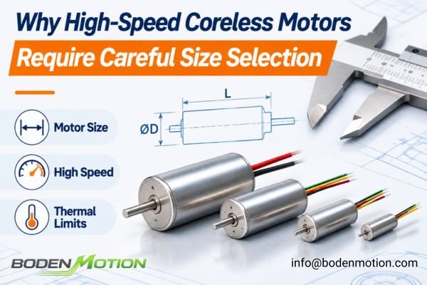
The final choice between a 6mm, 12mm, or 16mm coreless motor depends on the required torque, speed, load inertia, and thermal limits of the application. Diameter is a starting point that defines the physical envelope, not a complete performance specification.
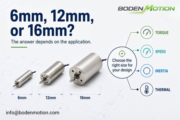
In OEM integration projects, the right motor is not the smallest one that fits—it is the smallest one that can still deliver the required performance with sufficient margin for reliability. This guide treats 6mm, 12mm, and 16mm as common cylindrical coreless motor size classes, covering both brushed and brushless technologies. While the internal structures differ, the general engineering principles of sizing remain consistent1.
What Changes When Coreless Motor Diameter Increases?
Assuming a larger diameter motor is simply "more powerful" is an oversimplification that can lead to over-engineering. The physical changes are more nuanced.
Increasing a coreless motor's diameter primarily expands the available electromagnetic and mechanical envelope. This creates the potential for higher performance and durability, but motor length remains an independent design variable.
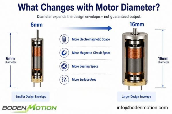
Moving from a 6mm to a 12mm or 16mm frame generally provides more radial space for:
- Active Electromagnetic Volume: Allows for more space for windings and magnetic components, creating greater potential for torque production.
- Magnetic Circuit: More room for the magnetic circuit can enable greater magnetic flux potential, depending on the motor topology, magnet grade, and electromagnetic design.
- Bearing System: Can accommodate larger, more robust bearings, which may improve radial and axial load capacity when designed accordingly.
- Heat Dissipation Area: A larger surface area can help the motor dissipate heat more effectively, improving its potential continuous torque capability.
System-Level Observation: Diameter indicates the available performance envelope, but actual output still depends heavily on the motor's length, winding design, operating voltage, and cooling conditions. A long, high-performance 12mm motor can sometimes outperform a short, entry-level 16mm motor in specific operating scenarios.
6mm Coreless Motors: When Minimum Size Matters Most
Engineers often face design constraints where every millimeter and every gram counts. This is the world where 6mm-class coreless motors provide unique value.
The primary advantage of a 6mm coreless motor is its extreme compactness and very low moving mass, making it ideal for applications where miniaturization and low inertia are the most critical design drivers.
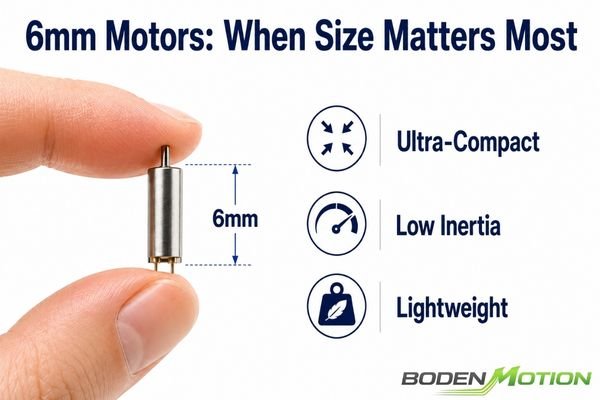
These motors are defined by their physical characteristics:
- Extremely compact diameter for tight integration.
- Very low rotor inertia, which supports rapid acceleration and direction changes in low-inertia systems.2
- Minimal weight, which is critical for handheld, portable, or wearable devices.
This makes them a strong choice for:
- Miniature medical pumps and drug delivery systems.
- Micro-actuators in optical instruments and lens focusing systems.
- Small, dexterous robotic fingers and grippers.
- Portable precision measurement tools.
However, from an integration perspective, their small size brings limitations. OEM engineers must carefully validate the application's demands against the motor's limited torque and thermal margin. Bearing load capacity and lifetime under continuous or high-cycle operation are critical checkpoints, as the smaller mechanical components can be more sensitive to overloading and wear.
12mm Coreless Motors: The Balance Between Size and Output
Many applications need more power than a 6mm motor can reliably provide but are still too space-constrained for a 16mm frame. This is the territory of the 12mm coreless motor.
12mm-class motors often represent a balanced compromise, offering a significant step up in torque and thermal potential from a 6mm motor while remaining compact, lightweight, and dynamically responsive.

Compared to the 6mm class, a 12mm motor typically provides:
- More winding volume for higher torque potential.3
- Better thermal margin for longer or more demanding duty cycles.
- Larger bearing options for greater load tolerance.
- A wider range of available gearbox and encoder configurations.
At the same time, they generally maintain a lower rotor inertia and smaller installation footprint than their 16mm counterparts. This balance makes them a workhorse in applications like medical handheld systems, precision laboratory automation, and compact robotic joints. A common sizing pattern in OEM applications is to evaluate the 12mm class when a 6mm motor would overheat and a 16mm motor would be too large and heavy.
16mm Coreless Motors: When Torque and Thermal Margin Become More Important
Choosing a 16mm motor isn't just about getting "more power." It's a deliberate engineering decision, often made when the application's demands for continuous torque or durability exceed the limits of smaller motors.
The move to a 16mm coreless motor is typically driven by a need for higher continuous torque, better thermal management for long duty cycles, or a more robust mechanical structure to handle heavier loads.
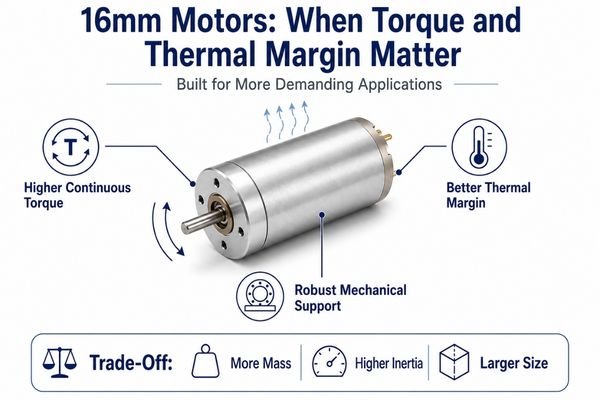
The larger frame of a 16mm motor can unlock several key engineering advantages:
- Higher Torque Capability: The increased electromagnetic volume allows for designs that can produce significantly more torque.
- Better Continuous Performance: Larger frames often provide more thermal capacity and heat-transfer area, but actual continuous torque still depends on the complete thermal path and operating environment.
- Stronger Mechanical Components: The ability to fit larger shafts and bearings can provide greater mechanical load capacity when the system is designed accordingly, which is important for durability in demanding applications.
This makes the 16mm class a go-to choice for robotic actuators, motorized surgical instruments, and high-load industrial automation. The trade-offs, of course, are higher motor mass, greater rotor inertia, and a larger installation volume.
6mm vs 12mm vs 16mm Coreless Motor Comparison
Looking at the general trends between these sizes helps clarify the initial selection process. But remember, this is a map of trends, not a list of absolute specifications.
This comparison shows the typical trade-offs an engineer makes when moving between these three common coreless motor diameters. The final choice must still be validated against the specific motor's datasheet and the application's operating point.
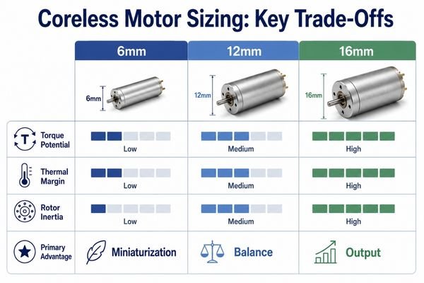
The table below outlines these general engineering trends.
| Selection Factor | 6mm Coreless Motor | 12mm Coreless Motor | 16mm Coreless Motor |
|---|---|---|---|
| Installation Space | Very small | Compact | Larger |
| Motor Weight | Typically lowest | Moderate | Typically higher |
| Rotor Inertia4 | Typically very low | Low to moderate | Typically higher |
| Torque Potential | Limited | Medium | Higher |
| Continuous Load Margin | Limited | Better potential | Higher potential |
| Thermal Capacity5 | Lowest | Moderate | Better potential |
| Bearing/Load Capability | Limited by size | Moderate potential | Better potential |
| Typical Priority | Miniaturization | Balance | Output and durability |
| Typical Application | Micro devices | Precision compact systems | Higher-load actuators |
These are directional indicators. The real performance of any motor is a function of its complete design—including length and winding. The datasheet for a specific model is always the source of truth.
How Torque, Speed, and Inertia Change the Size Decision
Moving beyond diameter requires looking at the physics of your application. The right motor size is determined by the work it needs to do.
The final decision on motor size is a multi-variable problem balancing the application's torque, speed, inertia, and thermal requirements against the motor's capabilities.
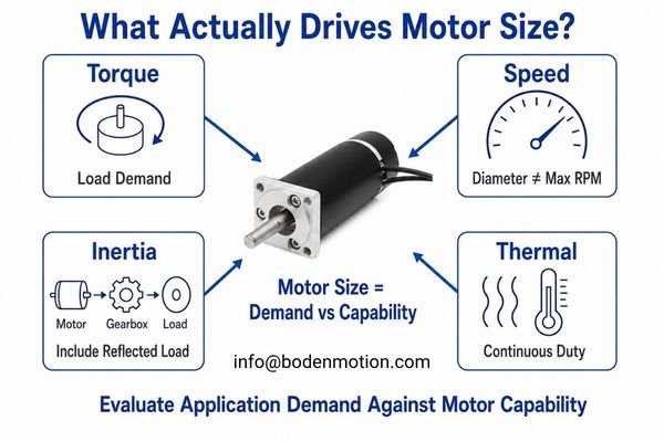
Torque Requirement
If the required load torque cannot be met by a smaller motor within its current and thermal limits, engineers may need to evaluate a larger diameter frame. The larger electromagnetic envelope provides more design margin for torque production, though the final solution also depends on motor length, winding, and gearbox selection.
Speed Requirement
High speed (RPM) is not exclusive to large or small motors. Allowable speed must be checked from the specific motor design and datasheet, as limiting factors may include bearing design, rotor balance, and the commutation system. Diameter is not a reliable predictor of maximum motor speed.
Load Inertia
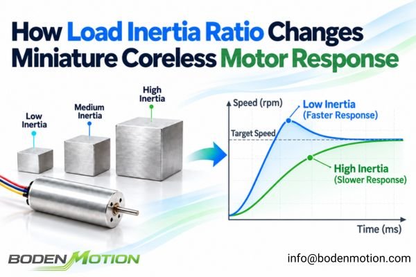
This is a common point of confusion. A 6mm motor's low rotor inertia is excellent for accelerating itself. But if it's connected to a high-inertia load, it may lack the torque (T = Jα) to accelerate the system quickly enough. The key is to evaluate the motor's torque capacity against the total system inertia (motor rotor + reflected load). When a gearbox is used, the load inertia reflected to the motor is reduced approximately with the square of the gear ratio6, so motor sizing should consider the complete motor–gearbox–load system.
Thermal Requirement
This is often the deciding factor in continuous-duty applications. Winding copper loss, a primary heat source, increases with I²R. Sustained operation near the motor's thermal limit can accelerate aging and reduce its service life7. A smaller motor may tolerate a demanding load for a short burst but be unsuitable when the same torque must be sustained continuously, where a larger motor with better thermal dissipation may be required.
Coreless Motor Size Selection Guide for OEM Engineers
A structured selection process helps prevent two common sizing problems: choosing a motor that operates too close to its torque or thermal limits, or oversizing the motor and adding unnecessary weight, space, and cost. As with broader DC motor selection, the process should begin with the real operating requirements rather than physical size alone.
Start with the application requirements, then evaluate the smallest motor size that can meet the real operating point with sufficient performance and thermal margin.
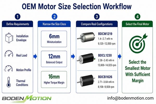
Here's a practical workflow for OEM teams:
- Define the Maximum Installation Envelope: Determine the maximum motor diameter and length your design can accommodate.
- Define the Real Load: Quantify continuous torque, peak/startup torque, and system friction.
- Define the Motion Requirements: Specify target speed, acceleration/deceleration time, and duty cycle.
- Analyze Thermal Conditions: Consider ambient temperature, enclosure conditions, mounting, and available cooling.
- Select the Smallest Size With Sufficient Margin: Confirm that a specific motor within the selected size class can meet the required torque, speed, and thermal conditions without continuously operating near its limits.
This quick-reference table can help narrow the initial size range:
| If Your Primary Requirement Is... | Your Likely Direction Is... |
|---|---|
| Extreme miniaturization & low weight8 | Start with the 6mm class |
| Compact size with moderate output | Evaluate the 12mm class |
| Higher torque or continuous load margin | Evaluate the 16mm class |
| Very fast acceleration of a heavy load | Prioritize torque-to-total-inertia ratio9 |
| Long continuous runtime | Prioritize thermal margin |
| High payload or external forces | Check shaft and bearing load capability |
Once the approximate size range is clear, the next step is to compare actual motor configurations rather than diameter alone.
Real 12mm and 16mm Coreless Motor Examples
BODENMOTION's published 12mm and 16mm platforms illustrate how motors within the same diameter class can still differ significantly in length, commutation architecture, torque, and speed. The examples below are therefore configuration references rather than a controlled size-only comparison.
BDCM1219 – Φ12×19mm Precious Metal Brushed Coreless DC Motor
11.5 g | 1–1.8 W | 1.4–2.7 mN·m rated torque | 9,120–12,000 rpm rated speed
BDCL1230 – Φ12×30mm Coreless Brushless DC Motor
14 g | 3–6 W | 2.38–2.43 mN·m rated torque | 13,600–14,025 rpm rated speed
BDCB1626 – Φ16×26mm Graphite Brushed Coreless DC Motor
24 g | 1.5–4 W | 2.71–3.64 mN·m rated torque | 8,108–9,928 rpm rated speed
The two 12mm motors alone show why diameter should remain only the first sizing filter. Motor length, brushed or brushless construction, winding design, torque, speed, duty cycle, and thermal conditions still determine which configuration is appropriate for the final OEM system.
Conclusion
6mm, 12mm, and 16mm coreless motors represent different trade-offs between installation size, inertia, torque potential, and thermal margin. Diameter is a useful first filter, but the final choice should be validated against the actual operating point, including torque, speed, load inertia, duty cycle, and thermal conditions.
For OEM projects, the goal is to select the smallest motor platform that can meet these requirements with sufficient performance and reliability margin. If you need help comparing motor sizes or configurations for a specific application, contact the BODENMOTION engineering team at info@bodenmotion.com.
FAQ
Q1: What is the main difference between 6mm, 12mm, and 16mm coreless motors?
The main difference is the available electromagnetic and mechanical volume. Larger diameters generally provide more potential for torque and thermal capacity, while smaller diameters provide lower weight and inertia.
Q2: Is a 16mm coreless motor always more powerful than a 12mm motor?
Not necessarily. Actual performance also depends on motor length, winding design, voltage, magnets, and thermal conditions. A long, high-performance 12mm motor can outperform a short 16mm motor in some cases.
Q3: Which coreless motor size is best for miniature robotics?
It depends on the joint size, payload, and motion cycle. Very small joints may favor 6mm motors for low inertia, while higher-load actuators may require 12mm or 16mm designs for sufficient torque.
Q4: Why not always choose the smallest coreless motor that fits?
An undersized motor may operate with insufficient torque margin, leading to excessive current draw, high temperature rise, and a significantly reduced operational lifetime.
Q5: What information should OEM engineers provide before selecting a coreless motor diameter?
Provide your maximum installation envelope (diameter and length), torque requirements (peak and continuous), target speed, load inertia, acceleration needs, duty cycle, thermal limits, and expected lifetime.
ISL Products, “Brushless vs Brushed Motors.” The guide compares brushed and brushless motor selection based on factors such as size, voltage, performance, and application requirements, supporting the use of a broadly consistent engineering sizing framework across both technologies. ↩
ScienceDirect, *Motor Inertia*, drawing on *Electric Motor Control* (2017). The rotational relationship `T_M − T_L = Jα` shows that lower inertia allows greater angular acceleration for a given available torque. The source also notes that motors intended for frequent acceleration and deceleration benefit from low rotor inertia. ↩
Rice University ECE, *The DC Motor*. For a cylindrical coreless motor, the text derives `T = NrBlI_a` and `K_t = NrlB`, showing that torque potential depends on active conductor turns, conductor length, radius, magnetic field, and current. Greater available winding space can therefore provide more design potential for torque production. ↩
ScienceDirect, *Motor Inertia*, drawing on *Electric Motor Control* (2017). The text explains that moment of inertia depends on mass distribution and radius, and states that a larger radius increases inertia. It also contrasts large-diameter, higher-inertia rotor designs with small-diameter, lower-inertia rotor designs. The size-class values shown here are directional trends rather than fixed specifications. ↩
Portescap, “Understanding the Thermal Parameters of Coreless DC Motors.” The white paper defines thermal capacitance as the ability of motor materials to absorb and store heat and relates it to material mass and specific heat capacity. The size-class comparison shown here should therefore be treated as a general trend rather than a universal specification. ↩
Motion Control Tips, “How do gearmotors impact reflected mass inertia from the load?” The article shows that load inertia reflected to the motor is reduced by the square of the gear ratio, commonly expressed as `J_reflected = J_load / N²` under the stated gear-ratio convention. ↩
ScienceDirect, *Motor Insulation*. The cited engineering references show that winding insulation life decreases rapidly as hot-spot temperature rises, including the commonly cited relationship that average insulation life is approximately halved for each 10°C increase. Operation near or beyond insulation temperature limits therefore reduces motor operating life and reliability. ↩
Orbray, “Small Motors (Mini Motors): Applications and Required Technology.” The article discusses ultra-miniaturized motors, including designs with outer diameters below 1 mm, and explains that coreless construction produces a lighter rotor. It supports miniaturization and low moving mass as key advantages of very small coreless motors. ↩
ScienceDirect, *Motor Inertia*, drawing on *Electric Motor Control* (2017). The motor-drive relationship `T_M = (J_M + J_L)dω/dt + T_L` shows that acceleration depends on available torque relative to total system inertia rather than motor torque or rotor inertia alone. In geared systems, the load inertia should first be reflected to the motor shaft. ↩