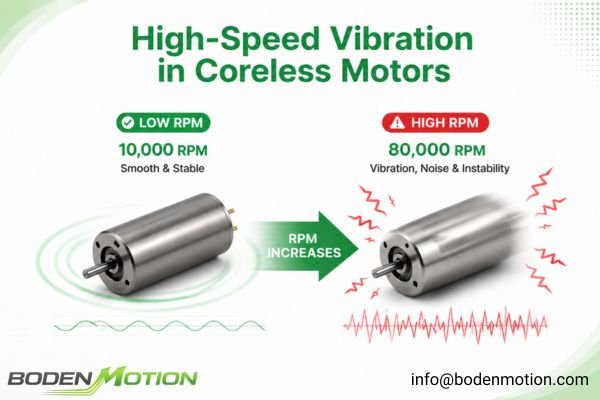
High-speed vibration is a frustrating problem. Your coreless motor system works perfectly at low RPM, but as you increase the speed, it starts to shake, generate noise, and lose stability.
This high-speed vibration in coreless motors is rarely due to a single fault. It is typically a system-level issue where the motor's low inertia makes it highly sensitive to small mechanical imperfections like rotor imbalance, bearing tolerances, and structural resonance, which are amplified by centrifugal forces at high RPM.
In many OEM integration projects, engineering teams select a coreless motor for its fast response and smooth low-speed control, only to discover that the entire device becomes unstable near the maximum operating speed. The truth is, high-speed stability isn't just about motor specifications; it's about the precise integration of the motor, the load, and the mechanical structure. Let's break down the common causes.
Why Coreless Motors Are More Sensitive to High-Speed Vibration
The defining feature of a coreless DC motor is its lightweight rotor, which has no iron core. This design significantly reduces rotor inertia, leading to performance advantages like extremely fast dynamic response and reduced cogging torque for smoother motion. However, this same characteristic is the reason it's more sensitive at high speeds.
Low rotor inertia means the motor has less mass to resist external disturbances and less inherent passive damping, making the entire system more susceptible to vibration.
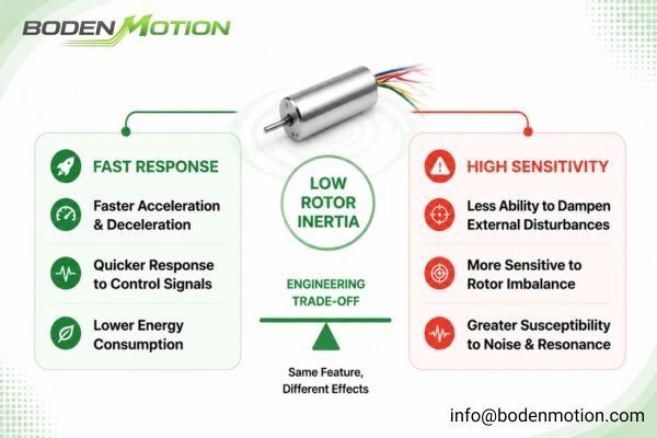
This is a classic engineering trade-off:
-
The Advantage of Low Inertia:
- Faster acceleration and deceleration with less current1
- Quicker response to control signals
- Lower energy consumption during speed changes
-
The Challenge of Low Inertia:
- Less ability to passively dampen mechanical vibration
- Increased sensitivity to any rotor imbalance
- Greater susceptibility to bearing noise and structural resonance
Coreless motors are not unstable by design. Rather, their superior responsiveness demands higher precision from the entire mechanical system to maintain stability during high-speed operation.
How Rotor Imbalance Becomes a Major Vibration Source at High RPM
Rotor imbalance is one of the most frequent culprits behind coreless motor vibration. The physics are straightforward: any mass not perfectly centered on the axis of rotation will create a centrifugal force as it spins.
This force grows with the square of the rotational speed (ω²). A tiny imbalance that is completely unnoticeable at 1,000 RPM can become a powerful shaking force at 20,000 RPM.
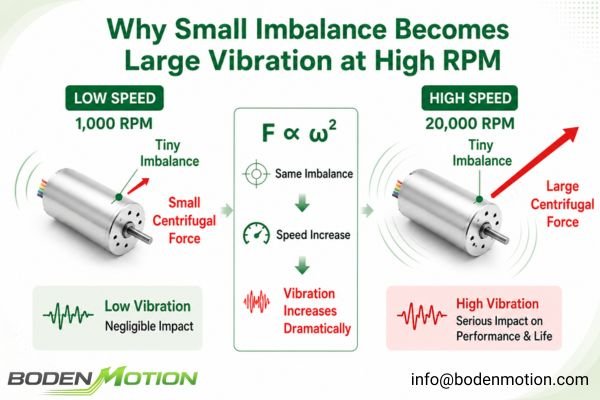
A common pattern during prototype testing is vibration that gets progressively worse as motor speed increases. This is a classic symptom of imbalance originating from manufacturing factors like:
- Minute variations in the rotor winding distribution
- Inconsistent thickness of adhesives used in assembly
- Slight eccentricity of the shaft relative to the rotor
- Manufacturing tolerances in rotor components
For this reason, dynamic balancing is essential for high-speed applications. ISO 21940 balance quality grades define allowable residual unbalance levels for rotating components. The required grade depends on the rotational speed, rotor mass, and the precision needs of the application.
| Balance Grade | Typical Application |
|---|---|
| G6.3 | General rotating machinery |
| G2.5 | Precision rotating equipment |
| G1.0 | High-speed precision systems |
| G0.4 | Ultra-precision applications |
Common OEM Mistake: Assuming that any "balanced" motor will work. A motor balanced to a G6.3 grade might be fine for a cooling fan, but it would likely cause unacceptable vibration in a 50,000 RPM dental handpiece, which may require a grade of G1.0 or better. The balance specification must match the speed and precision requirements of your device.
How Bearings and Mechanical Tolerances Affect High-Speed Stability
If the rotor is well-balanced but the system still shakes, the next place to look is the bearings and overall mechanical tolerances. At high speeds, bearings are no longer just simple supports; they become a critical component of the dynamic system.
Imperfections in bearings or shaft alignment that are negligible at low speeds can introduce significant radial runout, friction variation, and noise at high RPM, directly destabilizing the rotor.
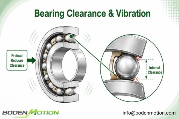
Engineers often find high-speed stability issues related to:
- Bearing Internal Clearance: The small gap between the balls and races can allow the rotor to "rattle" at high speeds.
- Bearing Preload: High-speed bearings are often preloaded (put under a light axial force) to remove this clearance. Too little preload causes chatter; too much causes excessive heat and premature failure.2
- Lubrication: The wrong type or amount of grease can increase friction and vibration. High-speed operation often demands specialized grease or oil.
- Shaft Runout and Alignment: An improperly seated bearing or a misaligned shaft forces the rotor to wobble, creating vibration.
High-speed stability depends on the complete bearing system design, including preload, lubrication, clearance, and operating conditions, not just the bearing's ABEC grade alone.3
Why Motor Installation Structure Can Amplify Small Vibrations
Sometimes, the motor itself is perfectly stable on a test bench, but it makes the entire device shake violently once installed. This is almost always a case of structural resonance.
Every mechanical structure has a natural frequency at which it prefers to vibrate. If the motor's operating RPM matches this frequency, even a tiny vibration from the motor can be amplified dramatically, just like pushing a child on a swing at the right moment.
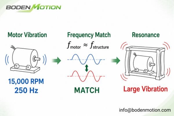
This is a common integration surprise, especially in devices with lightweight plastic housings or long, thin mounting brackets. A common OEM integration scenario illustrates this: a motor operating at 15,000 RPM creates a primary excitation frequency of 250 Hz (15,000 / 60). If a plastic housing or bracket has a natural frequency near 250 Hz, it will resonate loudly.4
Testing a motor on a heavy, rigid lab bench will not reveal these issues. The vibration only appears when the motor is installed in the final product assembly. Fixing resonance requires changing the system's stiffness or mass—perhaps by making a bracket thicker, adding support ribs, or using damping materials.
How Load Matching and Motor Control Influence High-Speed Vibration
A motor never runs in isolation. The connected load and the electronic driver are integral parts of the motion system, and both can be sources of high-speed vibration. Stability depends on the complete system: Motor + Controller + Load + Structure.
A mismatch between components can create a "tail wagging the dog" scenario, challenging the control system and leading to instability.
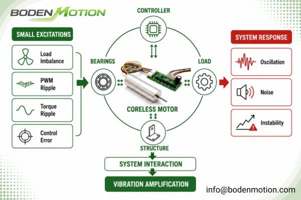
Mechanical Factors:
- Inertia Mismatch: A high load inertia connected to a low-inertia motor can cause overshoot and oscillation. As an engineering guideline, keeping the load-to-motor inertia ratio below 10:1 is often recommended for responsive servo systems5.
- Coupling Stiffness: A flexible coupling can introduce its own spring-like behavior and torsional vibrations, while a rigid coupling demands very precise alignment.
- Load Balance: An unbalanced load (like a fan blade or grinding bit) will create powerful vibrations that the motor cannot overcome.
Electrical and Control Factors:
- Torque Ripple: Even in brushless motors, ripple from commutation and winding harmonics can create excitation forces.
- PWM Current Ripple6: The driver's PWM scheme can introduce current ripple, leading to torque pulsations and audible noise.
- Control Loop Tuning: Poorly tuned PID gains can cause the motor to oscillate around its setpoint, appearing as speed fluctuation or vibration.
How OEM Engineers Should Evaluate High-Speed Coreless Motor Applications
To avoid high-speed vibration problems, the selection process must start with a complete system specification, not just a motor part number. Providing this information allows motor suppliers to evaluate whether a proposed motor can remain stable in the complete system.
In high-speed applications, the motor's rated speed alone is rarely enough to predict final performance. Factors such as load characteristics, mounting conditions, operating cycle, and control method can significantly affect vibration, noise, and long-term reliability. A complete application review helps identify potential integration risks before they appear during prototype testing or mass production.
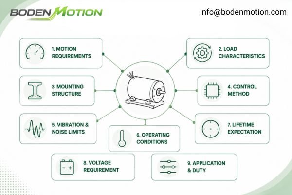
Before selecting a high-speed coreless motor, be prepared to define these critical parameters:
- Operating RPM: Maximum and continuous speed ranges.
- Torque Requirement: Continuous and peak torque at target speeds.
- Acceleration Profile: How quickly does the motor need to start and stop?
- Load Inertia7: The inertia of all components driven by the motor.
- Vibration & Noise Limits8: A quantifiable target (e.g., vibration in mm/s or g's, noise in dBA at a specific distance).
- Mounting Structure: Drawings or details of the motor mount, housing material, and stiffness.
- Operating Conditions: Ambient temperature and duty cycle.
- Lifetime Expectation: Required operating hours or cycles.
- Voltage Requirement: Available supply voltage and current limits.
- Control Method: The type of driver and feedback system (e.g., encoder, Hall sensors) being used.
High-Speed Coreless Motor Vibration Troubleshooting Guide
High-speed vibration troubleshooting requires separating motor-related problems from system-level problems. This systematic approach helps isolate the root cause by linking common symptoms to their likely origins.
A practical troubleshooting process usually starts by checking the simplest possible causes and gradually moving toward more complex system interactions. Engineers often compare the motor performance under different conditions, such as unloaded operation, final assembly testing, and different speed ranges, to determine whether the vibration originates from the motor itself or from the integrated system.
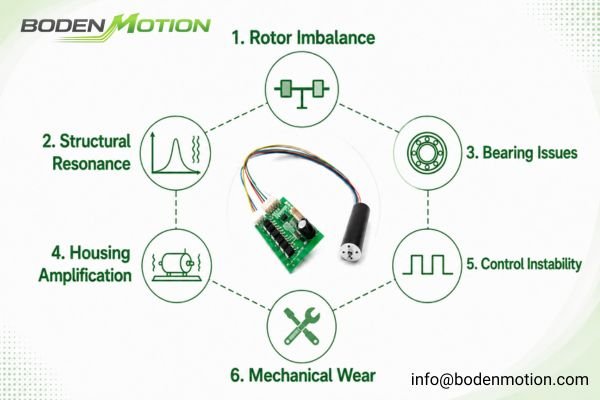
| Symptom | Possible Cause | Recommended Check |
|---|---|---|
| Vibration increases steadily with RPM | Rotor Imbalance9 | Run the motor uncoupled. If vibration persists and scales with speed, imbalance is likely. Verify the motor's balance grade. |
| Loud noise/vibration at a specific RPM | Structural Resonance10 | Slowly sweep the motor's speed. A sharp peak in vibration indicates resonance. Try temporarily stiffening the mount to see if the peak shifts. |
| High bearing temperature or audible whine | Bearing Issues | Check for incorrect preload, lubrication failure, or contamination. Verify the bearing grade and preload match the speed requirement. |
| Motor is stable alone, but noisy in device | Housing Resonance / Amplification | The motor is exciting a natural frequency of your device. Test the motor in the final assembly and consider FEA or structural modifications. |
| Speed fluctuation or oscillation | Control Instability / Torque Ripple | Review the inertia ratio and controller tuning (PID gains). Check for torque ripple or PWM-related noise from the driver. |
| Vibration appears after extended use | Mechanical Wear / Fatigue | Likely bearing wear or loosening of mechanical fasteners. This points to a component lifetime or fatigue issue. |
Conclusion
Coreless motors can deliver exceptional high-speed performance, but their low-inertia design requires a higher level of mechanical precision and system integration. High-speed stability is not achieved by selecting a motor with a high RPM rating alone; it is engineered through the interaction of rotor balance, bearing performance, mechanical structure, load characteristics, and control strategy.
For OEM engineers, the key to solving high-speed vibration is evaluating the complete motion system rather than focusing only on the motor datasheet. Our engineering team can review your application requirements and help identify potential integration risks to achieve reliable, quiet, and stable high-speed operation. Contact us at info@bodenmotion.com.
FAQ
Q1: Why do coreless motors vibrate more at high speed?
Coreless motors have very low rotor inertia, which improves response but also makes them more sensitive to imbalance, bearing variations, and external disturbances. These small imperfections generate forces that are amplified at high RPM, causing visible vibration.
Q2: Is rotor imbalance the main cause of high-speed vibration?
Rotor imbalance is one of the most common causes, as the resulting centrifugal force increases with the square of the speed. However, bearing condition, structural resonance, and load mismatch are also frequent contributors.
Q3: Can a balanced coreless motor still have vibration problems?
Yes. A well-balanced motor can still cause severe vibration if its operating frequency excites the natural resonant frequency of the device's mounting structure or housing. The problem is often the system, not just the motor.
Q4: Why are bearings important for high-speed coreless motors?
At high RPM, bearing precision, internal clearance, and lubrication condition directly dictate rotor alignment, rotational smoothness, noise, and long-term reliability. A low-quality bearing will undermine the performance of a high-precision motor.
Q5: What should OEM buyers provide when selecting a high-speed coreless motor?
OEM buyers should provide the full operating context: target RPM range, load inertia, details of the mounting structure, quantitative vibration/noise limits, duty cycle, ambient temperature, and the required system lifetime.
"Why Do Coreless Brushed DC Motors Respond Faster? - bodenmotion", https://bodenmotion.com/why-coreless-brushed-dc-motors-respond-faster/. A technical review from a research institution explains that lower rotor inertia in electric motors allows for faster acceleration and deceleration, as less torque is required to change the speed of the rotor, which can also reduce current draw during transient operations. Evidence role: mechanism; source type: research. Supports: Faster acceleration and deceleration with less current. Scope note: The source may discuss electric motors in general rather than only coreless motors. ↩
"Investigation of spindle bearing preload on dynamics and ...", https://mtrc.utk.edu/wp-content/uploads/sites/45/2019/09/ozturk_kumar_turner_schmitz_preload.pdf. A technical review by a bearing manufacturer and engineering textbooks confirm that preload is commonly applied to high-speed bearings to minimize internal clearance, and that improper preload can result in vibration (chatter) or excessive heat and bearing failure, though the optimal preload depends on the specific application and bearing type. Evidence role: mechanism; source type: education. Supports: High-speed bearings are often preloaded (put under a light axial force) to remove this clearance. Too little preload causes chatter; too much causes excessive heat and premature failure.. Scope note: The optimal preload values and failure modes may vary depending on bearing design and application. ↩
"Design of a high-speed reliable ball bearing", https://ntrs.nasa.gov/citations/19940028808. Engineering handbooks and technical standards indicate that high-speed bearing performance is influenced by system-level factors such as preload, lubrication, internal clearance, and operating conditions, and not solely by the ABEC grade, which primarily specifies dimensional tolerances. Evidence role: expert_consensus; source type: education. Supports: High-speed stability depends on the complete bearing system design, including preload, lubrication, clearance, and operating conditions, not just the bearing's ABEC grade alone.. Scope note: ABEC grade remains important for certain precision requirements, but is not the only determinant of high-speed stability. ↩
"Adjustments to Address Resonance - Vibration Testing - VRU", https://vru.vibrationresearch.com/lesson/adjustments-address-resonance/. This is supported by engineering literature on resonance, which explains that when the excitation frequency of a system matches its natural frequency, resonance occurs, often resulting in amplified vibrations and noise. Evidence role: mechanism; source type: education. Supports: If a plastic housing or bracket has a natural frequency near 250 Hz, it will resonate loudly.. Scope note: The specific frequency values and loudness depend on the system's geometry and material properties. ↩
"Inertia Ratio: Avoiding an Inertia Mismatch", https://pages.rexelusa.com/blog/automation/inertia-ratio. Technical literature on servo system design commonly recommends maintaining a load-to-motor inertia ratio below 10:1 to ensure stable and responsive performance, though some applications may tolerate higher ratios with advanced control strategies. Evidence role: expert_consensus; source type: education. Supports: As an engineering guideline, keeping the load-to-motor inertia ratio below 10:1 is often recommended for responsive servo systems.. Scope note: The 10:1 ratio is a general guideline and may vary depending on system design and control methods. ↩
"PWM power stage: Current ripple & Motor chokes", https://support.maxongroup.com/hc/en-us/articles/360005046213-PWM-power-stage-Current-ripple-Motor-chokes. Research on PWM-driven motors indicates that current ripple caused by pulse-width modulation can result in torque pulsations and increased audible noise, particularly at certain switching frequencies. Evidence role: mechanism; source type: paper. Supports: The driver's PWM scheme can introduce current ripple, leading to torque pulsations and audible noise.. Scope note: The magnitude of these effects depends on the specific motor and drive configuration. ↩
"Inertia and Motors", https://www.moog.com/news/ideas-in-motion-control/2003/11/inertia-and-motors.html. Engineering literature and motor selection guides emphasize that accurately calculating the total load inertia, including all driven components, is essential for proper motor sizing and dynamic performance. Evidence role: mechanism; source type: education. Supports: The inertia of all components driven by the motor (load inertia) must be considered during motor selection.. Scope note: The impact of load inertia may depend on the specific application and motion profile. ↩
"Understanding the ISO 10816-3 Vibration Severity Chart", https://acoem.us/blog/other-topics/understanding-the-iso-10816-3-vibration-severity-chart/. Industry guidelines and engineering standards recommend specifying vibration in units such as mm/s or g's and noise in dBA at a defined distance when selecting or evaluating electric motors, as this allows for objective comparison and compliance with regulatory requirements. Evidence role: expert_consensus; source type: institution. Supports: Vibration and noise limits should be defined in quantifiable terms such as mm/s, g's, or dBA at a specific distance when selecting a motor.. Scope note: The specific recommended limits may vary by application and industry. ↩
"Rotating unbalance", https://en.wikipedia.org/wiki/Rotating_unbalance. Engineering references indicate that rotor imbalance typically causes vibration amplitude to increase proportionally with rotational speed, supporting the association between steadily increasing vibration and imbalance; however, other faults can occasionally produce similar symptoms. Evidence role: mechanism; source type: encyclopedia. Supports: Vibration increases steadily with RPM is caused by rotor imbalance.. Scope note: Other mechanical faults may also cause increased vibration with RPM, so diagnosis should consider additional factors. ↩
"Structural dynamics", https://en.wikipedia.org/wiki/Structural_dynamics. Mechanical engineering literature explains that structural resonance occurs when the excitation frequency matches a system's natural frequency, resulting in a sharp increase in vibration amplitude at a specific RPM; this supports the claim that loud noise or vibration at a particular speed is indicative of resonance. Evidence role: mechanism; source type: encyclopedia. Supports: Loud noise or vibration at a specific RPM is caused by structural resonance.. Scope note: Other sources of vibration can coincide with resonance, so further analysis may be required for confirmation. ↩